Do you have a question about the Carrier 52S series and is the answer not in the manual?
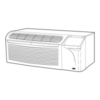
Examine the unit for damage incurred during shipment and file a claim if damage is found.
Use recommended wire size for a single branch circuit, complying with local and national codes.
Ensure the unit is grounded through the service cord plug or a separate ground wire for safety.
Ensure the outlet matches the plug and is within reach of the service cord. Refer to table for types.
Outlet must match plug, be within reach, and require accessory subbase for receptacle.
Low-voltage connections must be made for Energy Management Units and remote controls.
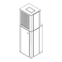
Units are shipped without sleeves. Follow requirements for proper sleeve installation in wall openings.
Remove center support and rear closure panel, and install outdoor grille as per instructions.
Inspect foam gaskets, lift chassis level, slide into sleeve, and screw securely to wall sleeve.
Install Carrier accessory hardwire kit or 265-v cord-connected kit according to provided instructions.
Disconnect power, remove terminal board cover, connect thermostat wires to chassis terminal board.
Install EM accessory kit in control box and connect low-voltage wires from chassis to central desk panel.
Modify discharge grille orientation for desired airflow direction, inverting if upward discharge is needed.
Slide the VENT knob manually to open or close the vent, it will remain in the selected position.
Adjust temperature range by restricting rotation of the temperature control knob for Econo Zone II.
Describes switch locations and functions for remote and unit control panels.
Details on OUTSIDE AIR, OFF, FAN ONLY, HIGH/LOW HEAT/COOL, and finding the right temperature setting.
Details the Fan Cycle Switch, Outdoor Thermostat, and Vent Control functions for unit operation.
The air inlet filter should be cleaned once each month by removing and cleaning it.
Clean the outdoor vent filter once during cooling or heating season, as it restricts airflow.
Disconnect all power to the unit before cleaning, servicing, or maintenance to avoid electrical shock.
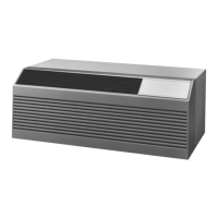
Clean external parts like polymer sleeve and grilles with household detergent and water.
Details the tools and steps required to disassemble the unit, including removing panels and chassis.
Clean indoor coil, stator, vent screen, basepan, blower wheel, and scroll using recommended methods.
Reassemble components by reversing disassembly procedures and reinstalling the unit into the sleeve.
An accessory polymer sleeve designed to protect against corrosion.
Optional grille available in aluminum or plastic for aesthetic and functional purposes.
Accessory for routing condensate away from the unit and building exterior.
An accessory subbase that does not include electrical components.
Accessory kit for lateral airflow applications, enabling duct connections.
Kit for controlling units remotely for energy conservation, especially in unoccupied rooms.
Accessory cord kit for connecting 265-volt units.
Accessory kit to convert cord-connected units to hardwired installations.
Retro-fit kit for adapting GE metal sleeves for Carrier units.
A standard grille accessory for the unit.
Accessory kit to secure the unit's control door.
An accessory thermostat that allows for programmable temperature scheduling.
A basic manual thermostat accessory for unit control.
Covers repair or replacement of defective parts within the first year of purchase at no charge.
Covers compressor, condenser, evaporator, or tubing defects for four years, including system charge.
Covers non-sealed system parts for four years, but excludes labor charges for repair.
Details limitations on implied warranties and exclusions like labor, shipping damage, and consequential damages.
Lists conditions and events for which Carrier is not responsible, such as lack of maintenance or misapplication.
Check plug, fuse/breaker, and control settings before calling for service to save money.
Contact your dealer or recommended service center as they handle most service problems efficiently.
Contact the local Carrier distributor if your dealer cannot provide a satisfactory solution.
Contact Carrier Air Conditioning Consumer Relations if issues persist after contacting dealer and distributor.
| Brand | Carrier |
|---|---|
| Model | 52S series |
| Category | Air Conditioner |
| Language | English |