58SB0B/58SB1B: Installation, Start–Up, Operating and Service and Maintenance Instructions
Manufacturer reserves the right to change, at any time, specifications and designs without notice and without obligations.
17
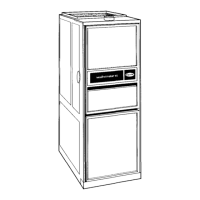
3. Remove the desired electrical box hole knockout and position the
hole in the electrical box over the hole in the furnace casing.
4. Fasten the electrical box to casing by driving two field supplied
screws from inside electrical box into casing steel.
A190278
Fig. 27 – Field-Supplied Electrical Box on Furnace Casing
5. Remove and save two screws holding J-Box.
6. Pull furnace power wires out of 1/2-in. (12 mm) diameter hole in
J-Box. Do not loosen wires from strain-relief wire-tie on outside of
J-Box.
7. Route furnace power wires through holes in casing and electrical
box and into electrical box.
8. Pull field power wires into electrical box.
9. Remove cover from furnace J-Box.
10. Route field ground wire through holes in electrical box and casing,
and into furnace J-Box.
11. Reattach furnace J-Box to furnace casing with screws removed in
Step 4.
12. Secure field ground wire to J-Box green ground screw.
13. Complete electrical box wiring and installation. Connect line
voltage leads (see Fig. 24). Use best practices (NEC in U.S. for
wire bushings, strain relief, etc.)
14. Reinstall cover to J-Box. Do not pinch wires between cover and
bracket.
Power Cord Installation in Furnace J-Box
NOTE: Power cords must be able to handle the electrical requirements
listed in Table 6. Refer to power cord manufacturer’s listings.
1. Remove cover from J-Box.
2. Route listed power cord through 7/8-in. (22 mm) diameter hole in
J-Box.
3. Secure power cord to J-Box bracket with a strain relief bushing or a
connector approved for the type of cord used.
4. Secure field ground wire to green ground screw on J-Box bracket.
5. Connect line voltage leads (see Fig. 24).
6. Reinstall cover to J-Box. Do not pinch wires between cover and
bracket.
BX Cable Installation in Furnace J-Box
1. Remove cover from J-Box.
2. Route BX cable into 7/8-inch diameter hole in J-Box.
3. Secure BX cable to J-Box bracket with connectors approved for the
type of cable used.
4. Secure field ground wire to green ground screw on J-Box bracket.
5. Connect line voltage leads (see Fig. 24).
6. Reinstall cover to J-Box. Do not pinch wires between cover and
bracket.
24-V Wiring
Make field 24-V connections at the 24-V terminal strip (see Fig. 20).
Connect terminal Y for proper cooling operation (see Fig. 28). Use only
AWG No. 18, color-coded, copper thermostat wire.
The 24-V circuit contains an automotive-type, 3-amp. fuse located on
the control. Any direct shorts during installation, service, or maintenance
could cause this fuse to blow. If fuse replacement is required, use ONLY
a 3-amp. fuse of identical size.
ACCESSORIES
1. Electronic Air Cleaner (EAC)
Connect an accessory Electronic Air Cleaner (if used) using 1/4-in
female quick connect terminals to the two male 1/4-in
quick-connect terminals on the control board marked EAC-1 and
EAC-2. The terminals are rated for 115 VAC, 1.0 amps maximum
and are energized during blower motor operation (see Fig. 28).
2. Humidifier (HUM)
Connect an accessory 24 VAC, 0.5 amp. maximum humidifier (if
used) to the 1/4-in male quick-connect HUM terminal and
COM-24V screw terminal on the control board thermostat strip.
The HUM terminal is energized when the pressure switch closes
during a call for heat (see Fig. 28).
NOTE: DO NOT connect furnace control HUM terminal to HUM
(humidifier) terminal on Thermidistatt, Zone Controller or similar
device. See Thermidistat, Zone Controller, thermostat, or controller
manufacturer’s instructions for proper connection.
NOTE: For 24-V & 115-V EAC or Humidifier Accessory details, see
Accessory instructions.
A210192
Fig. 28 – Furnace Control
 Loading...