14
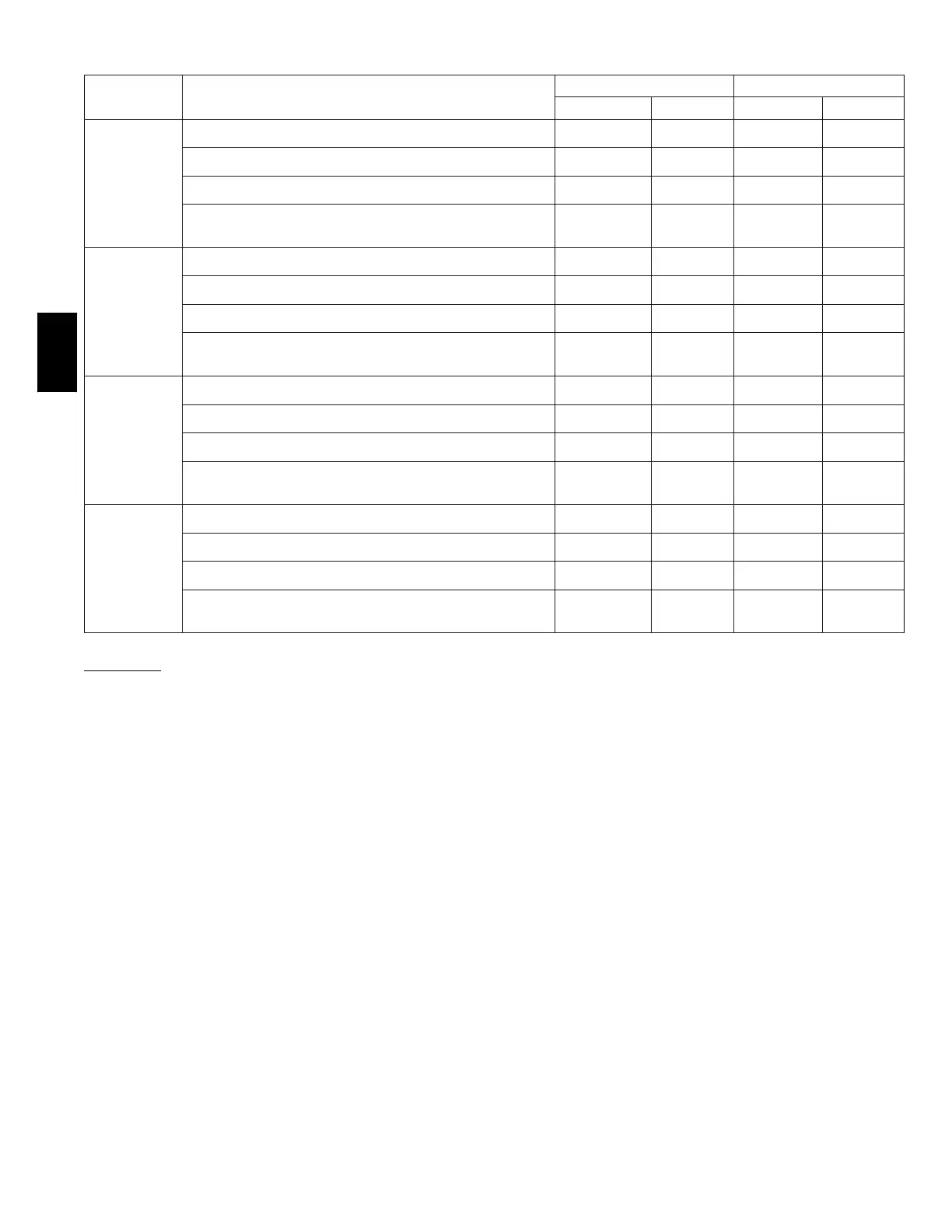
TABLE 4—OPENING DIMENSIONS (IN.)
FURNACE
CASING
WIDTH
APPLICATION
PLENUM OPENING FLOOR OPENING
A B C D
14–3/16
Upflow Applications on Combustible or Noncombustible Floor-
ing (KGASB subbase not required)
12---11/16 21---5/8 13--- 5/16 22--- 1/4
Downflow Applications on Noncombustible Flooring (KGASB
subbase not required)
12---9/16 19 13---3/16 19--- 5/8
Downflow applications on combustible flooring (KGASB sub-
base required)
11---13/16 19 13---7/16 20---5/8
Downflow Applications on Combustible Flooring with CD5 or
CK5 Coil Assembly or KCAKC coil box (KGASB subbase not
required)
12---5/16 19 13---5/16 20
17–1/2
Upflow Applications on Combustible or Noncombustible Floor-
ing (KGASB subbase not required)
16 21---5/8 16---5/8 22---1/4
Downflow Applications on Noncombustible Flooring (KGASB
subbase not required)
15---7/8 19 16---1/2 19---5/8
Downflow applications on combustible flooring (KGASB sub-
base required)
15---1/8 19 16---3/4 20---5/8
Downflow Applications on Combustible Flooring with CD5 or
CK5 Coil Assembly or KCAKC coil box (KGASB subbase not
required)
15---1/2 19 16---1/2 20
21
Upflow Applications on Combustible or Noncombustible Floor-
ing (KGASB subbase not required)
19---1/2 21---5/8 20--- 1/8 22---1/4
Downflow Applications on Noncombustible Flooring (KGASB
subbase not required)
19---3/8 19 20 19--- 5/8
Downflow applications on combustible flooring (KGASB sub-
base required)
18---5/8 19 20---1/4 20---5/8
Downflow Applications on Combustible Flooring with CD5 or
CK5 Coil Assembly or KCAKC coil box (KGASB subbase not
required)
19 19 20 20
24---1/2
Upflow Applications on Combustible or Noncombustible Floor-
ing (KGASB subbase not required)
23 21---1/8 23---5/8 22---1/4
Downflow Applications on Noncombustible Flooring (KGASB
subbase not required)
22---7/8 19 23---1/2 19---5/8
Downflow applications on Combustible flooring (KGASB sub-
base required)
22---1/8 19 23---3/4 20---5/8
Downflow Applications on Combustible Flooring with CD5 or
CK5 Coil Assembly or KCAKC coil box (KGASB subbase not
required)
22---1/2 19 23---1/2 20
AIR DUCTS
General Requirements
The duct system should be designed and sized according to
accepted national standards such as those published by: Air
Conditioning Contractors Association (ACCA), Sheet Metal and
Air Conditioning Contractors National Association (SMACNA)
or American Society of Heating, Refrigerating and Air
Conditioning Engineers (ASHRAE) or consult The Air Systems
Design Guidelines reference tables available from your local
distributor. The duct system should be sized to handle the
required system design CFM at the design external static pressure.
The furnace airflow rates are provided in Table 5--AIR
DELIVER Y--CFM (With Filter).
When a furnace is installed so that the supply ducts carry air
circulated by the furnace to areas outside the space containing the
furnace, the return air shall also be handled by duct(s) sealed to
the furnace casing and terminating outside the space containing
the furnace.
Secure ductwork with proper fasteners for type of ductwork used.
Seal supply-- and return-- duct connections to furnace with code
approved tape or duct sealer.
NOTE: Flexible connections should be used between ductwork
and furnace to prevent transmission of vibration. Ductwork
passing through unconditioned space should be insulated and
sealed to enhance system performance. When air conditioning is
used, a vapor barrier is recommended.
Maintain a 1 --in. clearance from combustible materials to supply
air ductwork for a distance of 36 in. horizontally from the
furnace. See NFP A 90B or local code for further requirements.
Ductwork Acoustical Treatment
NOTE: Metal duct systems that do not have a 90 degree elbow
and 10 ft. of main duct to the first branch take--off may require
internal acoustical lining. As an alternative, fibrous ductwork may
be used if constructed and installed in accordance with the latest
edition of SMACNA c onstruction standard on fibrous glass
ducts. Both acoustical lining and fibrous ductwork shall comply
with NFPA 90B as tested by UL Standard 181 for Class 1 Rigid
air ducts.
Supply Air Connections
For a furnace not equipped with a cooling coil, the outlet duct
shall be provided with a removable access panel. This opening
shall be accessible when the furnace is installed and shall be of
such a size that the heat exchanger can be viewed for possible
openings using light assistance or a probe can be inserted for
sampling the air stream. The cover attachment shall prevent leaks.
58ST