3
2-7/16"
1-1/8"
28-7/8"
25-1/4"
22-9/16"
JUNCTION BOX
LOCATION
7/8" DIA
ACCESSORY
1/2" DIA THERMOSTAT
WIRE ENTRY
3-15/16"
LEFT HAND GAS
ENTRY
33-5/16"
24-7/8"
5-1/2"
7/8" DIA. ACCESSORY
11/16"
21-5/8"
BOTTOM INLET
1-11/16"
13/16"
11/16"
4-13/16"
AIRFLOW
19"
OUTLET
13/16"
11/16"
8-9/16"
VENT OUTLET
5 PLACES (TYP)
3-3/4"
1-3/4" DIA.RIGHT HAND
GAS ENTRY
7/8" DIA. K.O. WIRE ENTRY
SIDE INLET
14-7/8"
7/8" DIA. ACCESSORY
1-1/4"
1"
22-1/16"
A
D
F
E
(FLUE COLLAR)
5-15/16"
24"
CASING
1-5/16"
1/2" DIA. K.O.THERMOSTAT
WIRE ENTRY
ALTERNATE
JUNCTION BOX
LOCATIONS (TYP)
26-1/8"
1-1/2"
7-3/4"
9-5/8"
11-1/2"
5-1/2"
NOTES:
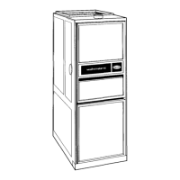
1. Two additional 7/8-in. diameter holes are located in the top plate.
2. Minimum return-air openings at furnace, based on metal duct. If flex duct is used, see flex duct manufacturer’s recommendations for equivalent diameters.
a. For 800 CFM-16-in. round or 14 1/2 x 12-in. rectangle.
b. For 1200 CFM-20-in. round or 14 1/2 x 19 1/2-in. rectangle.
c. For 1600 CFM-22-in. round or 14 1/2 x 22-in. rectangle.
d. For airflow requirements above 1800 CFM, see Air Delivery table in Product Data literature for specific use of single side inlets. The use of both side inlets
a combination of 1 side and the bottom, or the bottom only will ensure adequate return air openings for airflow requirements above 1800 CFM.
A04037
Fig. 1 --- Dimensional Drawing
1. Use only with type of gas approved for this furnace. Refer
to the furnace rating plate.
2. Install this furnace only in a location and position as
specified in the “Location” section of these instructions.
3. Provide adequate combustion and ventilation air to the
furnace space as specified in “Air for Combustion and
Ventilation” section.
4. Combustion product must be discharged outdoors.
Connect this furnace to an approved vent system only as
specified in the “Venting” section of these instructions.
5. Never test for gas leaks with an open flame. Use a
commercially available soap solution made specifically for
the detection of leaks to check all connections, as specified
in the “Gas Piping” section.
6. Always install furnace to operate within the furnace’s
intended temperature--rise range with a duct system which
has an external static pressure within the allowable range,
as specified in the “Start--Up, Adjustments, and Safety
Check” section. See furnace rating plate.
7. When a furnace is installed so that supply ducts carry air
circulated by the furnace to areas outside the space
containing the furnace, the return air shall also be handled
by duct(s) sealed to the furnace casing and terminating
outside the space containing the furnace. See Air Ducts
section.
8. A gas--fired furnace for installation in a residential garage
must be installed as specified in the warning box in the
Location section.
9. The furnace may be used for construction heat provided
that the furnace installation and operation complies with
the first CAUTION in the LOCATION section of these
instructions.
10. These Multipoise Gas--Fired Furnaces are CSA (formerly
A.G.A. and C.G.A.) design--certified for use with natural
and propane gases (see furnace rating plate) and for
installation in alcoves, attics, basements, closets, utility
rooms, crawlspaces, and garages. The furnace is
factory--shipped for use with natural gas. A CSA listed
accessory gas conversion kit is required to convert furnace
for use with propane gas.
11. See Fig. 2 for required clearances to combustible
construction.
12. Maintain a 1--in. clearance from combustible materials to
supply air ductwork for a distance of 36 inches
horizontally from the furnace. See NFPA 90B or local
code for further requirements.
13. These furnaces SHALL NOT be installed directly on
carpeting, tile, or any other combustible material other
than wood flooring. In downflow installations, factory
accessory floor base MUST be used when installed on
combustible materials and wood flooring. Special base is
not required when this furnace is installed on
manufacturer ’s Coil Assembly Part No. CAPV, CAPMP,
or CNPVP, or when Coil Box Part No. KCAKC is used.
See Fig. 2 for clearance to combustible construction
information.
INTRODUCTION
Series 120/C 4 --way multipoise Category I fan--assisted furnace is
CSA design--certified. A Category I fan--assisted furnace is an
appliance equipped with an integral mechanical means to either
draw or force products of combustion through the combustion
chamber and/or heat exchanger. The furnace is factory--shipped
for use with natural gas. This furnace is not approved for
installation in mobile homes, recreational vehicles, or outdoors.
This furnace is designed for minimum continuous return-- air
temperature of 60_F db or intermittent operation down to 55_F
db such as when used with a night setback thermostat. Return--air
temperature must not exceed 85_F db. Failure to follow these
return--air temperature limits may affect reliability of heat
exchangers, motors, and controls. (See Fig. 3.)
58ST