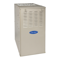
58SU0A (Series 2 & 3): Troubleshooting Guide
Manufacturer reserves the right to change, at any time, specifications and designs without notice and without obligations.
12
49. Turn power off and adjust blower speed to achieve higher airflow 36
50. Do you have continuity across the draft safeguard switch (DSS)? 54 51
51.
Allow draft safeguard switch (DSS) to cool for 10 minutes. Do you have continuity across the draft
safeguard switch (DSS)?
53 52
52. Replace draft safeguard switch. 10
53.
You may have excessive restriction in the vent system. Check the following
- Restriction in vent pipe
- Proper vent sizing for application
- Elbow baffle installed incorrectly in inducer outlet vent elbow
NOTE: If there are no signs of restriction, check for high winds. If there was no excessive wind, replace
the Draft Safeguard switch.
10
54.
Unplug the Blower Auxiliary limit switch connection at PL17. Measuring on the PL17 half that leads to
the blower housing, do you have continuity across PL17-1 and PL17-2?
68 55
55.
Allow the blower auxiliary limit switches (ALS) to cool for 10 minutes. Do you have continuity across the
blower auxiliary limit switches (ALS))?
57 56
56. Measure each (ALS) switch individually for continuity, and replace one or both that fail continuity test 10
57. Reconnect the Blower auxiliary limit switches (ALS) connection PL17 58
58.
Turn power on and jumper the R and W thermostat terminals. Allow furnace to operate for (2) 20-minute
cycles or until status code starts flashing
59
59. Does status code 13 flash? 61 60
60. Does a different status code flash? 5 11
61. Does the blower motor stop suddenly while running a heating cycle? 62 65
62. Remove jumper from the R and W terminals and allow blower motor to complete its blower-off delay 63
63. Turn power off 64
64.
Inspect blower harness connections at furnace control and (if applicable) at motor. If no harness defects
are found, replace blower motor
10
65. Remove jumper from the R and W terminals and allow blower motor to complete its blower-off delay 66
66. Turn power off 67
67.
Remove the blower housing and inspect the auxiliary blower switch harness paying particular attention
to where the harness meets the corners of the housing. If no defects are found, replace both blower
auxiliary limit switches
10
68. Reconnect the Blower auxiliary limit switches (ALS) connection PL17 69
69. Do you have continuity across the burner thermal switch (BTS)? 101 70
70. Allow the burner thermal switch (BTS) to cool for 10 minutes. 71
71. Can burner thermal switch (BTS) be reset? 73 72
72. Replace the burner thermal switch (BTS). 10
73.
Reset burner thermal switch (BTS) and turn power on. Jumper R and W thermostat terminals and
observe furnace operation for (2) 20 minute cycles.
74
74. Does the burner thermal switch (BTS) trip again? 76 75
75. Does a different status code flash? 5 11
76. Remove jumper from the R and W terminals and allow blower to operate for 5 minutes. 77
77. Turn off power and reset Burner Thermal Switch (BTS) 78
78.
Connect 1 side of a slope manometer with a tee to the collector box pressure tap. Refer to pressure
check connection illustration in APPENDIX B: Transducer Operational Check
79
79.
Check for proper transducer output. To do this, connect a DC voltmeter across terminals PL12-2
GREEN and PL12-3 BLACK (+).
80
80.
Run COMPONENT TEST by briefly shorting the TEST/TWIN terminal to the C terminal at the
thermostat terminal strip.
81
81.
Referencing the Voltage/Pressure graph located in APPENDIX D, compare the pressure from the slope
manometer to the output signal voltage from the transducer.
EXAMPLE: The graph illustrates that at 1" of negative pressure, the transducer output should be
approximately 1.5 VDC. At 3" of negative pressure, the transducer output should be approximately 3.5
VDC.
82
82. Is the transducer VDC output within +/- 0.15 VDC of the expected value? 84 83
83. Replace the transducer 10
84.
You have inadequate combustion-air through the burner box This may be caused by:
- Obstructed Air inlet elbow
- Clogged burner box mesh
- Leaking inducer housing gasket
- Leaking inducer choke plate seal
85
85. Turn off power and remove burner box 86
86. Inspect the burner box air inlet elbow for blockage 87
87. Inspect burner box mesh. Are there sign of deterioration or blockage? 88 92
88. Replace burner box assembly 10
89. Inspect Burner box mounting gasket. Are there signs of damage or deterioration? 90 91
90. Replace burner box gasket 10
91. Inspect and tighten (as needed) flame sense and igniter mounting screws 92
92. Reinstall burner box. Tighten mounting screws to 45 in. lbs. 93
STEP ACTION YES NO GO TO

 Loading...
