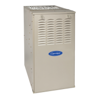
58SU0A (Series 2 & 3): Troubleshooting Guide
Manufacturer reserves the right to change, at any time, specifications and designs without notice and without obligations.
19
33. Turn off power and disconnect the jumper across the R and W thermostat terminals. 34
34. Connect a water column manometer or similar device to the gas valve outlet pressure port. 35
35. Turn on power and jumper across the R and W thermostat terminals. 36
36. Does the gas valve open and allow gas to flow? 38 37
37. Replace gas valve. 11
38.
Is the gas valve outlet pressure correct as specified in the Installation, Start Up, and Operating
Instructions?
40 39
39. Adjust gas valve pressure per the Installation, Start Up, and Operating Instructions. 11
40. Does the burner light and stay on longer than a few seconds? 41 43
41. Are there signs of combustion oscillation or pulsation? 42 8
42.
Check for:
Gas pressure fluctuation during heating cycle
Proper vent sizing for installation
Leakage in or around the heat exchanger
leakage between inducer and inducer housing
13
43. Turn off power and disconnect the jumper across the R and W thermostat terminals. 44
44.
Remove water column manometer or similar device from the gas valve outlet pressure port making
sure to fully close port
45
45.
Connect 1 side of a slope manometer with a tee to the collector box pressure tap. Refer to pressure
check connection illustration in APPENDIX C: Transducer Operational Check
46
46.
Check the transducer output signal. To do this, connect a DC voltmeter across terminals PL12-2
GREEN and PL12-3 BLACK (+).
47
47.
Turn power ON and run COMPONENT TEST by briefly shorting the TEST/TWIN terminal to the C
terminal at the thermostat terminal strip.
48
48.
Referencing the Voltage/Pressure graph located in Appendix D, compare the pressure from the
slope manometer to the output signal voltage from the transducer.
EXAMPLE: The graph illustrates that at 1" of negative pressure, the transducer output should be
approximately 1.5 VDC. At 3" of negative pressure, the transducer output should be approximately
3.5 VDC.
49
49. Is the transducer VDC output within +/- 0.15 VDC of expected value? 51 50
50. Replace transducer
51. Turn off power and remove burner box 53
52. Remove burner box assembly 53
53. Inspect burner box mesh for 54
54. Inspect the burner box air inlet elbow for blockage 55
55. Inspect burner box mesh. Are there sign of deterioration or blockage? 56 57
56. Replace burner box assembly 11
57. Inspect Burner box mounting gasket. Are there signs of damage or deterioration? 58 59
58. Replace burner box gasket 11
59. Remove and clean flame sensor with fine steel wool 60
60. Remove hot surface igniter and inspect gasket. Replace gasket if damaged 61
61. Reinstall flame sense electrode and igniter/gasket assembly 62
62. Reinstall burner box. Tighten mounting screws to 45 in. lbs. 63
63. Connect a DC microamp meter in series with the flame sensor wire 64
64. Turn power on and jumper R and W thermostat terminals. 65
65. When gas valve opens, is the DC current below .5 microamps? 69 66
66. When gas valve opens, is the DC current between .5 and 1.0 microamps? 67 25
67. Check connections and retry. 68
68. Inspect unit grounding 8
69. Replace flame sense electrode. 8
STEP ACTION YES NO GO TO

 Loading...
