6
pressure in the equipment room or space. A positive seal must be
made between the furnace cabinet and the return--air duct to
prevent pulling air from the burner area.
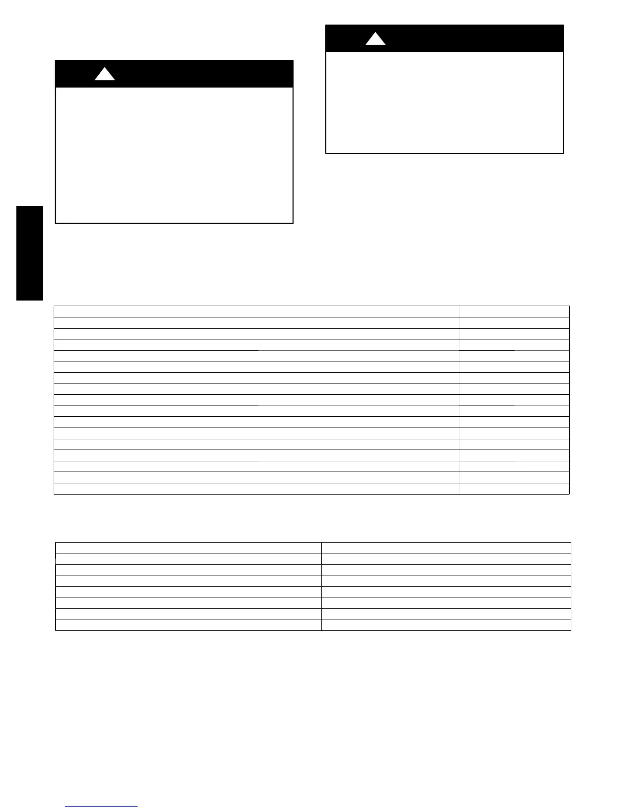
FIRE, INJURY OR DEATH HAZARD
Failure to follow this warning could result in personal
injury, death and/or property damage.
When the furnace is installed in a residential garage, the
burners and ignition sources must be located at least 18 in.
(457 mm) above the floor. The furnace must be located or
protected to avoid damage by vehicles. When the furnace is
installed in a public garage, airplane hangar, or other
building having a hazardous atmosphere, the furnace must
be installed in accordance with the NFPA 54/ANSI
Z223.1--2009 or CAN/CSA B149.2--2010. See Fig. 5.
!
WARNING
FIRE HAZARD
Failure to follow this warning could result in personal
injury, death and/or property damage.
Do not install the furnace on its back or hang furnace with
control compartment facing downward. Safety control
operation will be adversely affected. Never connect
return--air ducts to the back of the furnace. See Fig. 4.
!
WARNING
Location Relative to Cooling Equipment
The cooling coil must be installed parallel with, or on the
downstream side of the unit to avoid condensation in the heat
exchangers. When installed parallel with the furnace, dampers or
other flow control must prevent chilled air from entering the
furnace. If the dampers are manually operated, they must be
equipped with means to prevent operation of either unit unless the
damper is in the full--heat or full--cool position.
Table 1 – Factory--Supplied Installation Parts
DESCRIPTION QUANTITY
AirIntakePipeFlange 1
Vent Pipe Flange 1
Coupling Flange Gaskets 2
Sharp Tip Screws (Vent and Inlet Flanges) 10
Vent Pipe Coupling 1
Vent Pipe Coupling Clamps 2
Rubber Drain Elbow 1
Drain Tube Clamps 4
1 / 2 --- i n . C P V C t o 3 / 4 --- i n . P V C P i p e A d a p t e r 1
Gas Line Grommet 1
Junction Box Cover 1
Junction Box Base 1
Green Ground Screw 1
Blunt Tip Screws (Junction Box) 3
Thermostat Wire Gr ommet 1
Drain Extension Tube (Z---pipe) (Provided separately in furnace) 1
Table 2 – Minimum Clearances to Combustible Materials for All Units
POSITION CLEARANCE
Rear 0(0mm)
Front (Combustion air openings in furnace and in structure) 1in.(25mm)
Required for service *24 in. (610 mm)
All Sides of Supply Plenum *1 in. (25 mm)
Sides 0(0mm)
Vent 0(0mm)
Top of Furnace 1in. (25mm)
* Consult local building codes.
59MN7A