13
REFRIGERANT LINES
General refrigerant line sizing:
1 The 619FB/538FR units ar e shipped with a full cha rge of
R410A refr i ger ant. All cha rges , li ne si zing, and ca pac ities are
base d on runs of 25 ft (7. 6 m). For runs over 25 ft (7.6 m),
consul t the long--line sect i on on this page for proper charge
adjustments.
2 Minimum refrigerant line length between the indoor and
outdoor units is 10 ft. (3 m).
3 Ref rigerant lines shoul d not be burie d in the ground. If it is
nece ssary to bury the li nes, not more tha n 36--in (914 mm)
should be buried. Provide a minim um 6--in (152 mm) ver t ic a l
rise to the se rvice valves to prevent refrige r ant migration.
4 Both lines must be insulated. Use a minimum of 1/2--in.
(12.7 mm) thick insulation. A closed-- cell insulation is
recommended in all long --line applications.
5 Spec ial considerat i on should be given to isol at i ng
interconnecting tubing from the building structure. Isolate the
tubing so that vibration or noise is not transmitted into the
structure.
IMPORTANT: Both refrigerant lines must be insulated separately.
S The following maximum lengths are allowed:
System Size
9K
(208--230V)
12K
(208--230V)
18k
(208--230V)
Piping
Min. Piping Length ft (m) 10 (3) 10 (3) 10 (3)
Standard Piping
Length
ft (m) 25 (7.6) 25 (7.6) 25 (7.6)
Max. outdoor--indoor
height difference
ft (m) 32.8 (9.9) 32.8 (9.9) 32.8 (9.9)
Max. Piping Length
with no additional
refrigerant charge
ft (m) 25 (7.6) 25 (7.6) 25 (7.6)
Max. Piping Length ft (m) 82 (25) 82 (25) 82 (25)
Additional refrigerant
charge (between
Standard – Max
piping length)
Oz/ft
(g/m)
0.2 (18.6) 0.2 (18.6) 0.2 (18.6)
Gas Pipe (size --
connection type)
in
1/2 Flare
connection
1/2 Flare
connection
5/8 Flare
connection
Liquid Pipe (size --
connection type)
in
1/4 Flare
connection
1/4 Flare
connection
1/4 Flare
connection
Refrigerant
Refrigerant Type R410A R410A R410A
Charge Amount
Lbs
(kg)
3.1 (1.4) 3.1 (1.4) 4.4 (2)
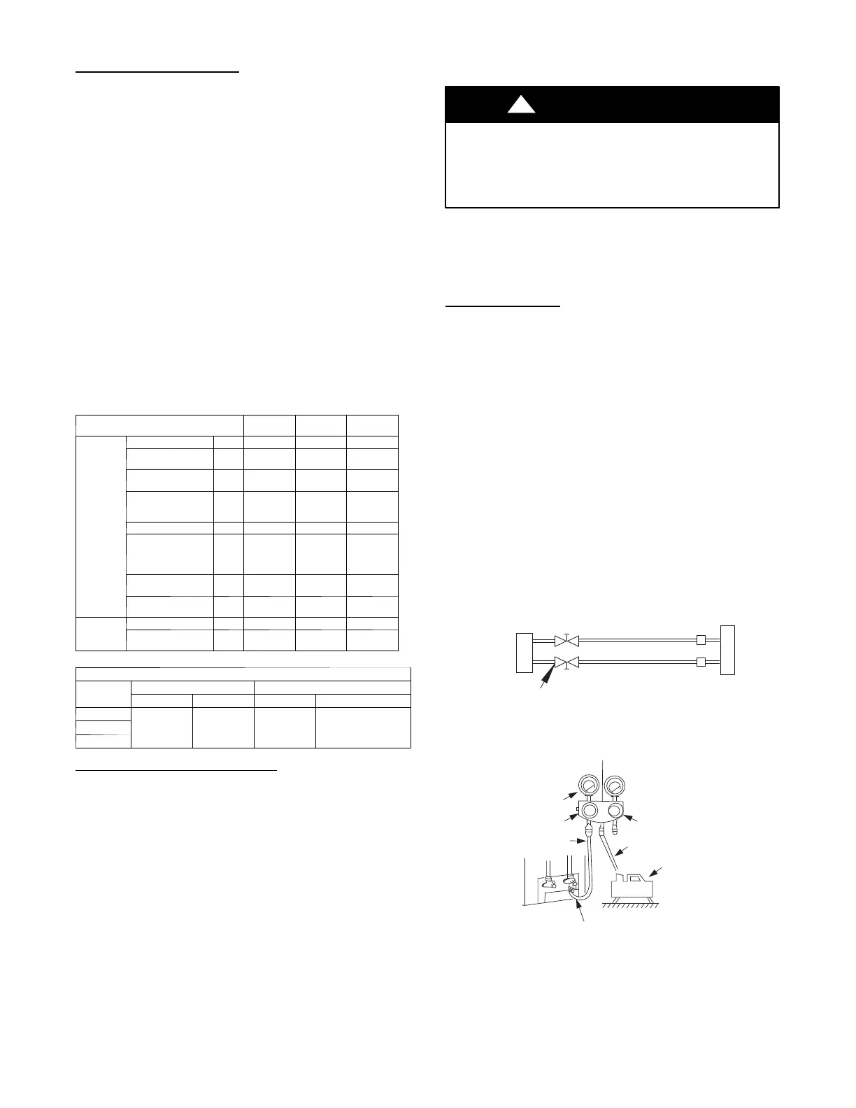
ADDITIONAL REFRIGERANT CHARGE TABLE
Unit Size
Total Line Length ft. Additional Charge oz/ft. ft (m)
Min Max 10--25 (3 -- 8) >25--82 (8--25)
9
10 82 None 0.0212
18
Long Line Applications Units:
1 No change in line sizing is required.
2 Add refrigerant per Additional Charge table.
SYSTEM EVACUATION AND
CHARGING
UNIT DAMAGE HAZARD
Failure to follow this caution may result in equipment
damage or improper operation.
Never use the system compressor as a vacuum pump.
CAUTION
!
Refrigerant tubes and indoor coil should be evacuated using the
recommended deep vacuum method of 500 microns. The alternate
triple evacuation method may be used if the procedure outlined
below is followed. Always break a vacuum with dry nitrogen.
System Vacuum and Charge
Using Vacuum Pump
1 Completely tighten flare nuts A, B, C, D, connect manifold
gage charge hose to a charge port of the low side service
valve (see Fig. 14).
2 Connect charge hose to vacuum pump.
3 Fully open the low side of manifold gage (see Fig. 15).
4 Start vacuum pump.
5 Evacuate using either deep vacuum or triple evacuation
method.
6 After evacuation is complete, fully close the low side of
manifold gage and stop operation of vacuum pump.
7 The fa ctory charge cont ai ned in the outdoor unit is good for up
to 25 ft. (8 m) of li ne length. For refriger ant lines longer than
25 ft (8 m), add refr i ge r a nt as spec i f i e d in the ADDITIONAL
REFRIGERANT CHARGE TABLE on this page.
8 Disconnect charge hose from charge connection of the low
side service valve.
9 Fully open service valves B and A.
10 Securely tighten caps of service valves.
Outdoor Unit
Indoor Uni
Refrigerant
Service Valve
Low Side
High Side
A
B
C
D
Fig. 14 – Service Valve
Manifold Gage
500 microns
Low side valve
High side valve
Charge hose
Charge hose
Vacuum pump
Low side valve
Fig. 15 – Manifold


 To Next Page
 Loading...