EasyManua.ls Logo

Carrier 69NT40-561-201 User Manual

Carrier 69NT40-561-201
117 pages
To Next Page IconTo Next Page
Page #1 background imageLoading...
Page #1 background image
T364 Rev A
OPERATION & SERVICE MANUAL
For
69NT40-561-201
Evergreen Container Refrigeration Units
Container Refrigeration

Table of Contents

Questions and Answers:

Carrier 69NT40-561-201 Specifications

General IconGeneral
Model69NT40-561-201
RefrigerantR-410A
Phase1
Compressor TypeScroll
Operating Voltage208-230V

Summary

Safety Summary

General Safety Notices

Basic safety precautions for operation and maintenance of the equipment covered.

Specific Warning and Caution Statements

Detailed warnings and cautions regarding hazards and unsafe conditions.

Introduction to the Unit

Unit Overview and Identification

General introduction to the unit and how to identify its configuration.

Key Unit Features

Detailed descriptions of various components and features of the unit.

Unit Description

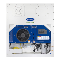
General Description and Front Section

Overall unit description and components accessible from the front.

Evaporator, Compressor, and Condenser Sections

Description of the evaporator, compressor, and condenser sections and their components.

Control Box and Communications Module

Details on the control box contents and the communications interface module.

Unit Specifications

Refrigeration System Data

Technical data for the refrigeration system including components and specifications.

Electrical Data

Electrical specifications, parameters, and data for unit components.

Safety and Protective Devices

Information on safety features and protective mechanisms integrated into the unit.

Refrigeration Circuit Operation

Details on standard, economized, and EEV operation of the refrigeration circuit.

Microprocessor Control System

System Overview and Components

Description of the microprocessor system, including keypad, display, and controller.

Controller Software and Modes

Details on controller software, configuration, operational codes, and modes of operation.

Defrost, Protection, and Alarms

Procedures for dehumidification, cooling/heating, defrost, protection modes, and controller alarms.

DataCORDER Functions and Pre-Trip Tests

Pre-trip diagnostics, DataCORDER description, software, configurations, alarms, and ISO trip header.

Controller Configuration, Function Codes, and Alarms

Configuration variables, function codes, and detailed alarm indications.

Pre-Trip Test Codes

Detailed descriptions of various pre-trip test codes for system diagnostics.

Unit Operation

Pre-Operation Inspection and Power Connection

Steps for inspecting the unit before operation and connecting power safely.

Air Makeup Vent, Monitoring, and Starting/Stopping

Adjusting vent, connecting monitoring, and unit start/stop procedures.

Start-Up Inspection and Pre-Trip Diagnosis

Detailed startup checks and pre-trip diagnostic procedures.

Probe Diagnostics

Procedures for diagnosing temperature probe issues and ensuring accuracy.

Troubleshooting Common Issues

Unit Start-Up and Cooling Problems

Diagnosing issues with unit starting, stopping, and continuous cooling.

Heating, Defrost, and Pressure Issues

Troubleshooting insufficient heating, defrost failures, and abnormal pressures.

Noise, Malfunctions, and Airflow Problems

Addressing noise, microprocessor issues, airflow restrictions, and EEV malfunctions.

Temperature, Current, and Compressor Issues

Troubleshooting abnormal temperatures, currents, and compressor operation.

Service Procedures and Tools

Section Layout and Manifold Gauge Set

Overview of the service section and basic tool usage for system diagnostics.

Service Connections and Pump Down

Procedures for making service connections and pumping down the unit.

Refrigerant Handling

Refrigerant Leak Checking

Methods for detecting refrigerant leaks in the system.

Evacuation and Dehydration

Procedures for removing moisture and air from the refrigeration system.

Refrigerant Charge Procedures

Steps for checking and adding refrigerant to the system.

Compressor and High Pressure Switch Service

Compressor Removal and Replacement

Step-by-step guide for safely removing and replacing the compressor.

High Pressure Switch Service

Procedures for checking and replacing the high pressure switch.

Condenser Service

Condenser Coil Service

Procedures for cleaning, removing, preparing, and installing the condenser coil.

Condenser Fan and Filter Drier Service

Procedures for servicing the condenser fan motor and filter drier.

Evaporator and EEV Service

Evaporator Coil and Heater Service

Procedures for evaporator coil and heater replacement.

Evaporator Fan Motor and Section Cleaning

Replacing fan motor assembly and cleaning the evaporator section.

Electronic Expansion Valve Service

Procedures for replacing the Electronic Expansion Valve (EEV).

Valve Service

Economizer and Digital Unloader Valve Service

Service procedures for economizer solenoid, expansion valves, and digital unloader valve.

Valve Override Controls

Using valve override controls for troubleshooting and timed operations.

Controller and Sensor Service

Controller Handling and Troubleshooting

Guidelines for handling controller modules and basic troubleshooting.

Software Programming and Controller Replacement

Procedures for software loading, controller replacement, and battery replacement.

Temperature Sensor Service and Replacement

Detailed procedures for checking and replacing various temperature sensors.

Vent Position Sensor (VPS) Service

Procedures for servicing the vent position sensor and its calibration.

Unit Maintenance and Installation

Painted Surface Maintenance

Guidelines for maintaining the unit's painted surfaces against corrosion.

Communications Interface Module Installation

Steps for installing the communications interface module.

Electrical Wiring Schematics

Introduction to Schematics

Overview of the electrical wiring schematics section.

Component Legend

Explanation of symbols used in electrical diagrams.

Schematic and Wiring Diagrams

Visual representation of the unit's electrical systems.

Related product manuals