EasyManua.ls Logo

Carrier 68RV11302A - User Manual

Carrier 68RV11302A
49 pages
To Next Page IconTo Next Page
Loading...
R
Transport Air Conditioning
T--298 Rev D
SERVICE MANUAL
for
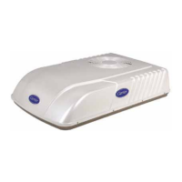
MODEL AirV
Rooftop Air Conditioning Systems
R
Transport Air Conditioning
2P
C
F
H
1
2
BLK
BLU
WHT
WHT
EVAP.
GRN/YEL
WHT
BRN
1
2
YEL
RED
BLU
R
C
S
RED
PTC
BLU

Table of Contents

Questions and Answers:

Carrier 68RV11302A Specifications

General IconGeneral
Voltage208/230V
Phase1
Frequency60 Hz
RefrigerantR-410A
SEER Rating13
Seasonal Energy Efficiency Ratio (SEER)13
Operating Temperature (Cooling)65°F to 115°F

Summary

SAFETY SUMMARY

GENERAL SAFETY NOTICES

General safety notices for unit operation and maintenance.

SPECIFIC WARNING AND CAUTION STATEMENTS

SPECIFIC WARNINGS AND CAUTIONS

Specific warnings and cautions applicable to the refrigeration unit.

SECTION 1 DESCRIPTION

1.1 INTRODUCTION

Overview of the AirV unit, its systems, and configurations.

1.2 SERIAL NUMBER IDENTIFICATION

Guide to identifying unit model and serial numbers.

1.3 DESIGN CHANGE DESCRIPTIONS

List of design changes and associated serial number breaks.

1.4 AirV SYSTEM COMPONENT SPECIFICATIONS

Technical specifications for AirV system components.

1.5 START-UP

Guidance on starting up the AirV unit.

1.6 REFRIGERANT CYCLE-STANDARD SYSTEM

Explanation of the standard system's cooling cycle operation.

1.7 REFRIGERANT CYCLE - HEAT PUMP

Explanation of the heat pump system's cooling and heating cycles.

SECTION 2 TROUBLESHOOTING

2.1 NO POWER TO UNIT

Troubleshooting steps for unit power loss.

2.2 DUCTED UNIT WILL NOT OPERATE

Troubleshooting steps for a non-operating ducted unit.

2.3 DUCTED UNIT WILL NOT COOL

Troubleshooting steps for a ducted unit failing to cool.

2.4 COMPRESSOR POWER SUPPLY OPEN

Troubleshooting for an open compressor power supply.

2.5 COMPRESSOR RUNS BUT CYCLES, FAN OPERATING ERRATICALLY

Troubleshooting for compressor cycling and erratic fan operation.

2.6 CYCLES ON COMPRESSOR OVERLOAD

Troubleshooting for unit cycling due to compressor overload.

2.7 INSUFFICIENT COOLING, COOLING AIR NOT ADEQUATE

Troubleshooting for insufficient cooling or inadequate cooling air.

2.8 CONDENSER AIR NOT ADEQUATE

Troubleshooting for inadequate condenser air flow.

2.9 INSUFFICIENT COOLING

Troubleshooting steps for general insufficient cooling.

2.10 COMPRESSOR FLOODING

Troubleshooting for compressor flooding issues.

2.11 HEATER CYCLES ON LIMIT SWITCH (HEAT; COOL VERSION ONLY)

Troubleshooting for heater cycling on limit switch.

2.12 AIR SWEEP NOT WORKING (FREE BLOW VERSION ONLY)

Troubleshooting for the air sweep function not working.

2.13 WATER LEAKAGE

Troubleshooting steps for water leakage from the unit.

2.14 INADEQUATE HEAT (FREE-BLOW HEAT ONLY)

Troubleshooting for inadequate heat in free-blow models.

2.15 INADEQUATE HEAT (HEAT-PUMP)

Troubleshooting for inadequate heat in heat-pump models.

SECTION 3 SERVICE AND MAINTENANCE

3.1 PREVENTATIVE MAINTENANCE

Routine cleaning and inspection procedures for unit maintenance.

3.2 SERVICE - GENERAL

General notes and guidance for servicing AirV units.

3.3 CEILING UNIT - FREE BLOW SYSTEMS

Service procedures for free-blow ceiling units.

3.4 CEILING UNIT - DUCTED SYSTEMS

Service procedures for ducted ceiling units.

3.5 SERVICE - UPPER UNIT - STANDARD, HC & HP

Service procedures for standard, HC, and HP upper units.

3.6 SERVICE - UPPER UNIT - LOW PROFILE

Service procedures for low profile upper units.

3.7 THERMOSTAT INSTALLATION AND START-UP INSTRUCTIONS (WALL MOUNTED)

Guide for installing and starting up wall-mounted thermostats.

3.8 LCD DISPLAY

Information on the LCD display for thermostats.

3.9 SET THERMOSTAT CONFIGURATION

Steps to configure thermostat settings.

3.10 CHECK THERMOSTAT OPERATION

Procedures for checking thermostat operation modes.

3.11 CHECK THERMOSTAT OPERATION

Procedures for checking thermostat operation parameters.

SECTION 4 WIRING SCHEMATICS

4.1 INTRODUCTION

Introduction to the wiring schematics for AirV units.

4.2 WALL MOUNTED THERMOSTATS

Wiring diagrams for wall-mounted thermostats.

Related product manuals