15
Apply the factory provided gasketing material to the top of
the horizontal base. Follow the rigging directions in the
Step 6 — Rig and Place Unit section to place the ERV on the
horizontal base. Position the ERV so that the ERV's LCD (liq-
uid crystal diode) display is on the opposite side of the horizon-
tal base's duct openings. Secure the ERV to the horizontal base
using 1-in. self-tapping sheet metal screws every 18 in. around
the perimeter.
NOTE: The ERV may also be mounted to the horizontal base
prior to being set on the roof curb.
Install Ductwork
— Ductwork will be connected to the hori-
zontal box (62EB-EU units) or directly to the ERV (62E2-E7
units) for stand-alone horizontal discharge and exhaust applica-
tions. See Fig. 12 for the horizontal box connection dimen-
sions. See Fig. 10 for 62E2-E7 connection dimensions. Do not
support the duct from the horizontal box. Provide field
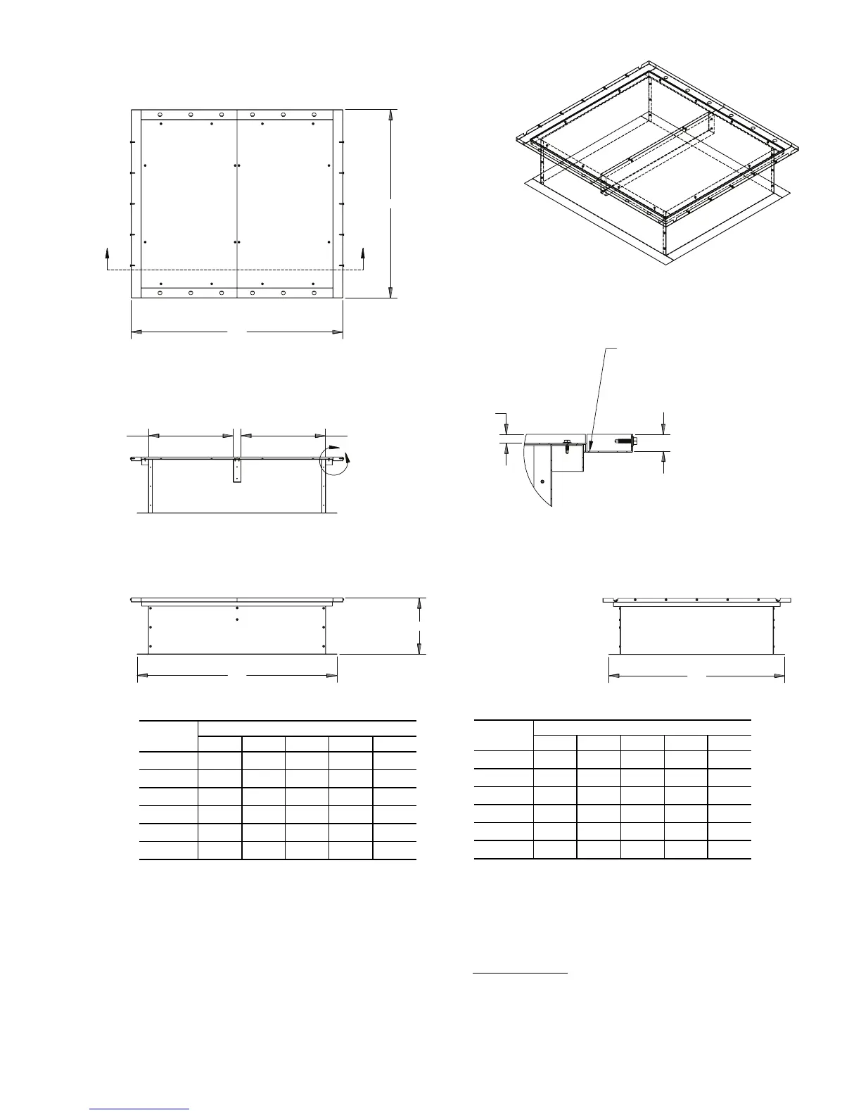
"A"
14.559
"C"
"D"
AA
"E"
"B" I.D. "B" I.D.
B
SECTION A-A
.941
.500
DETAIL B
SCALE 1 : 3
ERV RAIL SITS DOWN
IN CHANNEL
62E UNIT
TYPE
DIMENSIONS (in.)
ABCDE
7 28.286 10.143 31.397 36.927 33.816
2 35.882 13.941 38.993 40.446 37.335
3 41.682 16.841 44.793 40.306 37.195
4 51.882 21.941 54.993 48.826 45.715
5 64.302 28.151 67.413 54.286 51.175
6 74.882 33.441 77.993 60.236 57.125
a62-442
NOTE: Dimensions are in inches.
Fig. 11 — 62E2-62E7 Unit Roof Curb Dimensions
62E UNIT
TYPE
DIMENSIONS (mm)
ABCDE
7 718 258 797 938 859
2 911 354 990 1027 948
3 1059 428 1138 1024 945
4 1318 557 1397 1240 1161
5 1633 715 1712 1379 1300
6 1902 849 1981 1530 1451