Do you have a question about the Carrier A07051 and is the answer not in the manual?
| Operating Temperature | 32°F to 122°F (0°C to 50°C) |
|---|---|
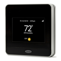
| Connectivity | Wi-Fi |
| Power Source | 24 VAC |
| Remote Access | Yes, via mobile app |
| Voice Control | Amazon Alexa, Google Assistant |
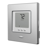
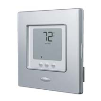
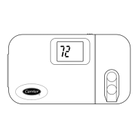
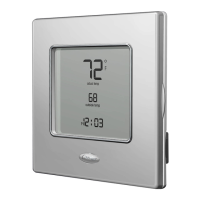
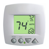
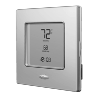
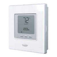
Details the four models in the Comfort Series: programmable/non-programmable, AC/HP.
Explains dual power sources (batteries, 24VAC) and wiring requirements for Comfort Series thermostats.
Provides guidelines for selecting the optimal location for thermostat mounting.
Covers the physical installation process, including wiring and mounting the thermostat base.
Guides the installer through setting configuration options for proper thermostat operation.
Details how to use the built-in installer test to verify thermostat and equipment functionality.
Describes the Home, Away, Sleep feature for programmable models, allowing preset temperature setpoints.
Explains clock operation and battery backup for programmable thermostat models.
Details battery operation, installation, and power source changeover for the thermostat.
Explains the two levels of display lighting and their availability based on power source.
Describes how the door switch affects display behavior and user functions.
Details mounting hole configurations for junction boxes on programmable and non-programmable models.
Explains Rc/Rh terminal connections for separate 24VAC transformers for heating and cooling.
Provides guidelines for wire gauge and length for thermostat wiring applications.
Details the O/B terminal function for heat pump reversing valves and configuration options.
Explains various operational timers like compressor timeguard, minimum on, and cycle timers.
Describes error codes indicating thermostat sensor or memory failures and their remedies.