Do you have a question about the Carrier SYSTXCCITN01-A and is the answer not in the manual?
Configure the system's time and date settings for accurate operation.
Enter installer contact details for service and support.
General overview of the installation process for the Infinity Touch Control and Wireless Access Point.
Inspect all equipment upon arrival to ensure it is undamaged and complete.
Guidelines for optimal placement of the wall control and sensors for accurate readings.
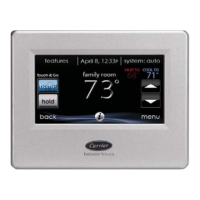
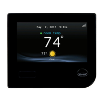
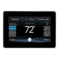
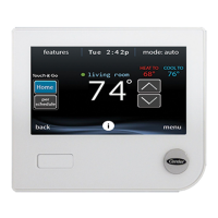
Specific placement recommendations for the Infinity Touch Wall Control.
Guidelines for placing remote room sensors for optimal temperature sensing.
Method for averaging readings from multiple remote room sensors.
Information on using smart zone sensors in zoning systems.
Important factors and guidelines for proper system wiring.
Using shielded wire to prevent interference in installations.
Details on the Damper Control Module for zoning systems.
Steps and considerations for mounting the Infinity Touch Control.
Information on the optional decorative backplate for mounting.
How to connect humidifiers to the system.
Wiring instructions for bypass humidifiers.
Wiring instructions for fan powered humidifiers.
The control searches for and identifies the indoor equipment.
The control searches for and identifies the outdoor equipment.
Select the indoor evaporator coil for accurate refrigerant charge calculations.
Select the size of the electric heater for the system.
Information on configuring hydronic heat applications.
View a summary of all installed system components and their configurations.
Access installation-related settings and options within the service menu.
Configure various system parameters and settings.
Adjust thermostat settings like auto mode, deadband, and offsets.
Configure automatic system mode switching based on time.
Set the temperature difference between heating and cooling modes.
Calibrate temperature and humidity sensors for accuracy.
Restore system settings to factory default values.
Enable or disable the system's scheduling features.
Configure the system's smart energy-saving recovery function.
Configure settings specific to the fan coil unit.
Select appropriate airflow settings for the fan coil based on installation needs.
Adjust settings based on the installation altitude for accurate pressure readings.
Configure dehumidification settings for the fan coil unit.
Define the operation for the fan coil's G-terminal.
Configure alerts for the fan coil's G-terminal status.
Set a custom label for the fan coil G-terminal alert.
Configure settings specific to the furnace unit.
Select appropriate airflow settings for the furnace during heating.
Configure airflow for AC/Heat Pump operation and dehumidification.
Control the staging sequence and low-stage run times for the furnace.
Set minimum and maximum airflow limits for modulating furnaces.
Configure the blower run time after heating has shut off.
Adjust furnace airflow compensation based on altitude.
Set the time for the fan to turn off for coil draining after cooling.
Define the operation for the furnace's G-terminal.
Configure alerts for the furnace G-terminal status.
Set a custom label for the furnace G-terminal alert.
Configure settings specific to AC and Heat Pump units.
Configure high cool and high heat latch settings for the unit.
Set the outdoor temperature below which cooling will not operate.
Set the time interval for heat pump defrost cycles.
Enable low ambient cooling operation for the outdoor unit.
Enable quiet shift mode for communicating heat pumps.
Set the maximum operating speed for variable capacity heat pumps.
Configure outdoor unit fan delay after defrost cycles.
Disable the high voltage brownout detection function.
Adjust airflow speed for non-communicating two-stage units.
Input published ratings for energy tracking calculations.
Set lockout temperatures for different heat sources.
Configure stages and latch settings for 18VS heat pumps.
Configure settings for Geothermal Heat Pump systems.
Set the temperature limit for loop liquid drop before unit stops.
Set the number of trips before compressor lockout.
Control the high voltage brownout override function.
Configure parameters for zoning systems.
Enable or disable the zoning functionality.
Adjust temperature offsets for each zone sensor.
Select airflow noise relationship for each zone.
Select the time for daily duct assessment.
Configure settings for installed accessories.
Configure filter settings, pressure monitoring, and clean intervals.
Configure humidifier installation, fan speed, and pad change intervals.
Configure UV light installation and maintenance intervals.
Set the cleaning interval for the ventilator.
Configure utility curtailment and saver functions.
Select airflow for fan coil when paired with a hydronic coil.
Exercise the electric heaters in three stages to verify operation.
Verify proper installation and operation of the furnace.
Exercise the hydronic heat relay and blower for verification.
Exercise the air conditioner's low and high cooling stages.
Exercise the heat pump's heating stages, speeds, and defrost options.
Exercise the heat pump's cooling stages and speeds.
Exercise the humidifier operation by turning it On and Off.
Exercise the ventilator through all operating speeds.
Perform checks on zoning system components and airflow.
Assess and adjust airflow noise limits for each zone.
Verify operation of zone dampers and correspondence of zone sensors.
Review results of the zone duct assessment.
View a list of zones and their corresponding sensor types.
Access likely root causes for recent system faults.
View relevant operational information for the fan coil.
View relevant operational information for the furnace.
View relevant operational information for the AC unit.
View relevant operational information for the heat pump.
View relevant operational information for the Geo HP unit.
View relevant operational information about the zoning operation.
Review the last 10 recorded system events with time and date.
Access resettable faults, cycle counters, and run times for system components.
View model and serial numbers of installed system equipment.
View contact information for future system service.
View energy usage data for system components.
Guide for entering lineset length, vapor line diameter, and verifying charge.
Upload dealer logo and contact information using a USB drive.
Steps to establish Wi-Fi connectivity for SYSTXCCITC01-A models.
Steps to establish Wi-Fi connectivity for SYSTXCCITW01-A models.
| Product Type | Thermostat |
|---|---|
| Model Number | SYSTXCCITN01-A |
| Brand | Carrier |
| Type | Smart Thermostat |
| Connectivity | Wi-Fi |
| Display | Touchscreen |
| Color | White |
| Display Type | LCD |
| Operating Temperature | 32°F to 122°F (0°C to 50°C) |
| Humidity Control | Yes |
| Remote Access | Yes |
| Programmable | Yes |
| Energy Star Certified | Yes |
| Compatibility | HVAC systems |
| Control | App |
| Energy Saving Features | Geofencing |
| Power Source | Battery |