82
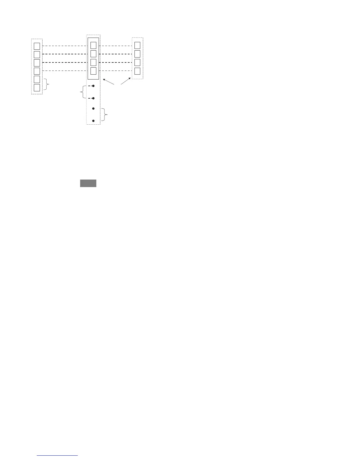
8. Wiring Diagrams
A
B
C
D
A
B
C
D
User Interface
Green - Data A
Yellow - Data B
White - COM
Red - 24VAC
OAT
Optional Remote
Room Sensor
HUM
COM
24V
Humidifier
Connection
S2
S1
A
B
C
D
ABCD
Connections
Communicating
AC or HP*
Green
Yellow
White
Red
OAT
Sensor
(Optional)
Variable-Speed
Furnace/ Fan Coil
*NOTE: Some outdoor units do not require the “C” and “D” connections.
See outdoor unit Installation Instructions.
*NOTE: For SPP products, ABCD connection between Indoor and Outdoor
control boards are pre-wired at the factory.
*NOTE: For new SPP installations in which the OAT Sensor is required,
please refer to the SPP Installation Instructions.
A13124
Universal Four--Wire Connection

 Loading...