1--2
T--304
04/08
1.2 GENERAL DESCRIPTION
1.2.1 Rooftop Unit
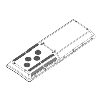
The rooftop unit includes the condenser section and the evaporator section (See Figure 1--1).
AC310
AC350
Condenser Section
Evaporator Section
Condenser Section
Evaporator Section
Figure 1--1 AC310/350 Rooftop Units
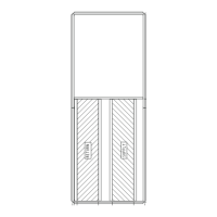
1.2.2 Condensing Section
The dual (See Figure 1--2) and single loop (See
Figure 1--3) condensing sectionsincludethecondenser
coils, four (4) or six (6) fan and motor assemblies,
filter-driers, receivers, and filter drier service valves.
The condenser coils provide heat transfer surface for
condensing refrigerant gas at a high temperature and
pressure into a liquid at high temperature andpressure.
The condenser fans circulate ambient air across the
outside of the condenser tubes at a temperature lower
than refrigerant circulating inside the tubes; this results
in condensation of the refrigerant into a liquid. The
filter-drier removes moisture and debris from the liquid
refrigerant before it enters the thermostatic expansion
valve in the evaporator assembly. The service valves
enable isolation of the filter-drier for service.
The receiver collects and stores liquid refrigerant. The
receiver is also fitted with a pressure relief valve which
protects the system from unsafe high pressure
conditions.