EasyManua.ls Logo

Carrier AQUAZONE 50PCV030 User Manual

Carrier AQUAZONE 50PCV030
60 pages
To Next Page IconTo Next Page
Page #1 background imageLoading...
Page #1 background image
Manufacturer reserves the right to discontinue, or change at any time, specifications or designs without notice and without incurring obligations.
Catalog No. 04-53500266-01 Printed in U.S.A. Form 50PC-6SI Pg 1 1-2020 Replaces: 50PC-5SI
Installation, Start-Up, and
Service Instructions
CONTENTS
Page
SAFETY CONSIDERATIONS . . . . . . . . . . . . . . . . . . . 2
GENERAL . . . . . . . . . . . . . . . . . . . . . . . . . . . . . . . . . . . 2
PRE-INSTALLATION . . . . . . . . . . . . . . . . . . . . . . . . . . 2
•INSPECTION
STORAGE
INSTALLATION . . . . . . . . . . . . . . . . . . . . . . . . . . . . . . 2
Step 1 — Check Jobsite . . . . . . . . . . . . . . . . . . . . . . . 2
HORIZONTAL UNITS (50PCH)
VERTICAL UNITS (50PCV)
INSTALLATION GUIDELINES (ALL UNITS)
Step 2 — Check Unit . . . . . . . . . . . . . . . . . . . . . . . . . . 3
INSPECT UNIT
Step 3 — Locate Unit . . . . . . . . . . . . . . . . . . . . . . . . . 8
•PROTECTION
Step 4 — Mount the Unit . . . . . . . . . . . . . . . . . . . . . . . 8
DUCT FLANGES
HORIZONTAL UNITS (50PCH)
VERTICAL UNITS (50PCV)
Step 5 — Check Duct System . . . . . . . . . . . . . . . . . . 9
HORIZONTAL SUPPLY AIR CONFIGURATION
CONVERSION
Step 6 — Install Condensate Drain . . . . . . . . . . . . . 10
Step 7 — Pipe Connections . . . . . . . . . . . . . . . . . . . 10
WATER LOOP APPLICATIONS
GROUND LOOP APPLICATIONS
INSTALLING SUPPLY AND RETURN HOSE KIT
UNITS WITH WATERSIDE ECONOMIZER OR
BOILERLESS HEAT CONTROL
AQUASTAT BULB INSTALLATION
Step 8 — Wire Field Power Supply . . . . . . . . . . . . . 11
HIGH VOLTAGE
Step 9 — Wire Control Connections . . . . . . . . . . . . 22
COMPLETE C AND DELUXE D CONTROL
THERMOSTAT AND DDC SENSORS
HOT GAS REHEAT CONTROL
AUXILIARY RELAY (DELUXE D ONLY)
ENERGY MANAGEMENT SWITCH (DELUXE D
ONLY)
BOILERLESS HEAT CONTROL (DELUXE D ONLY)
ALARM OUTPUT (ALL UNITS)
WSHP OPEN CONTROL
CONTROL TRANSFORMER
Step 10 — Configure Unit Control Components . . 23
UNIT PROTECTION MODULE (UPM)
WATERSIDE ECONOMIZER
BOILERLESS HEAT CONTROL (DELUXE D ONLY)
PRE-START-UP . . . . . . . . . . . . . . . . . . . . . . . . . . . . . 24
System Checkout . . . . . . . . . . . . . . . . . . . . . . . . . . . 24
CLEAN AIR COIL
Set Blower Motor Speed . . . . . . . . . . . . . . . . . . . . . . 25
PERMANENT SPLIT CAPACITOR (PSC) MOTOR
CONSTANT TORQUE (ECM) MOTOR
System Flushing and Filling . . . . . . . . . . . . . . . . . . .29
System Flow . . . . . . . . . . . . . . . . . . . . . . . . . . . . . . . .29
FLOW VERIFICATION
FLOW REGULATION
ANTIFREEZE
FREEZE PROTECTION SELECTION
START-UP . . . . . . . . . . . . . . . . . . . . . . . . . . . . . . . . . .30
Operating Limits . . . . . . . . . . . . . . . . . . . . . . . . . . . .30
ENVIRONMENT
•POWER SUPPLY
UNIT STARTING CONDITIONS
Start-Up Procedure . . . . . . . . . . . . . . . . . . . . . . . . . .30
SCROLL COMPRESSOR ROTATION
COOLING MODE START-UP
HEATING MODE START-UP
OPERATION . . . . . . . . . . . . . . . . . . . . . . . . . . . . . . . .39
Power Up Mode . . . . . . . . . . . . . . . . . . . . . . . . . . . . .39
Unit Protection Module (UPM) . . . . . . . . . . . . . . . . .39
Units with Complete C or Deluxe D Controls . . . . .39
STANDBY
COOLING
HOT GAS REHEAT (OPTIONAL)
WATERSIDE ECONOMIZER (OPTIONAL)
TWO WAY WATER FLOW CONTROL VALVE
(OPTIONAL)
BOILERLESS HEAT (DELUXE D ONLY)
PUMP/VALVE RELAY (DELUXE D ONLY)
Units with WSHP Open Controls . . . . . . . . . . . . . . .39
COOLING
REVERSE CYCLE HEATING
TWO POSITION OA DAMPER
MODULATING OA DAMPER WITH DCV
AUXILIARY MODULATING HOT WATER / STEAM
HEATING REHEAT
2-POSITION HOT WATER / STEAM HEATING
REHEAT
SINGLE STAGE ELECTRIC AUXILIARY HEAT
AUTOMATIC FAN SPEED CONTROL
FAN SPEED CONTROL - DURING HEATING
FAN SPEED CONTROL - DURING COOLING
MODULATING WATER ECONOMIZER CONTROL
2-POSITION WATER ECONOMIZER CONTROL
POWER FAIL RESTART DELAY
SUPPLY AIR TEMPERATURE MONITORING /
CONTROL / ALARM
DEHUMIDIFICATION
SPACE TEMPERATURE ALARMS
CONDENSER WATER TEMPERATURE MONITORING
/ CONTROL / ALARM
HIGH CONDENSATE / OVERFLOW ALARM
FILTER STATUS ALARM
COMPRESSOR FAULT/LOCKOUT ALARM
INSUFFICIENT VENTILATION ALARM
RELATIVE HUMIDITY ALARM
TIME SCHEDULES
Aquazone™
50PCH, PCV 007-070
Compact Water Source Heat Pumps
with Puron
®
Refrigerant (R-410A)
Question and Answer IconNeed help?

Do you have a question about the Carrier AQUAZONE 50PCV030 and is the answer not in the manual?

Carrier AQUAZONE 50PCV030 Specifications

General IconGeneral
Model50PCV030
RefrigerantR410A
Sound Pressure Level45 dB(A)
TypeHeat Pump
Power Supply50Hz

Summary

SAFETY CONSIDERATIONS

PRE-INSTALLATION

Procedures for checking unit upon receipt and preparing for installation.

STORAGE

Guidelines for storing units if not immediately installed.

INSTALLATION

Step 1 - Check Jobsite

Reviewing installation, operation, and maintenance instructions before unit start-up.

Step 2 - Check Unit

Inspecting the unit for damage and verifying correct model and components upon receipt.

Step 3 - Locate Unit

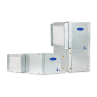
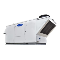
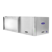
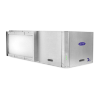
Selecting an appropriate indoor location for the unit, ensuring service access.

Step 4 - Mount the Unit

Instructions and procedures for securely mounting the unit.

Step 5 - Check Duct System

Verifying ductwork capacity and insulation for optimal performance.

Step 6 - Install Condensate Drain

Connecting and properly pitching the condensate drain line for effective drainage.

Step 7 - Pipe Connections

Guidelines for making water loop and ground loop piping connections.

Step 8 - Wire Field Power Supply

Instructions for safely wiring the unit's main power supply according to codes.

Step 9 - Wire Control Connections

Connecting control wiring for thermostats, DDC, and other components.

Step 10 - Configure Unit Control Components

Setting up and configuring unit protection modules and safeties for proper operation.

START-UP AND OPERATION

System Checkout

Final checks before energizing the unit and initial start-up procedures.

ANTIFREEZE

Guidelines for using antifreeze in the system for freeze protection.

UNIT STARTING CONDITIONS

Recommended operating limits for unit start-up based on temperatures.

Start-Up Procedure

Step-by-step instructions for initiating unit start-up and verifying operation.

SCROLL COMPRESSOR ROTATION

Verifying correct compressor rotation direction for proper operation.

COOLING MODE START-UP

Procedures for initiating and verifying unit operation in cooling mode.

HEATING MODE START-UP

Procedures for initiating and verifying unit operation in heating mode.

OPERATION

Overview of unit operating modes and control sequences.

Power Up Mode

Initial power-up sequence and compressor anti-short cycle delay.

Unit Protection Module (UPM)

UPM sequence of operations for unit safeties and protection.

Units with Complete C or Deluxe D Controls

Operating modes and features for Complete C and Deluxe D controls.

Units with WSHP Open Controls

Features and operation for WSHP Open DDC controls.

SERVICE AND TROUBLESHOOTING

SERVICE

Periodic maintenance procedures and recommendations for optimal unit performance.

Filters

Guidelines for filter inspection, cleaning, and replacement intervals.

Condenser Cleaning

Procedures for cleaning water-cooled condensers to prevent fouling.

TROUBLESHOOTING

Identifying and resolving common unit operational issues and faults.

UNIT PROTECTION MODULE (UPM)

Understanding UPM functions, safeties, and fault indicators.

Freeze Sensor

Configuration and function of freeze protection sensors.

Thermistor

Role of thermistors in system operation and freeze protection.

Thermostatic Expansion Valves

Function, purpose, and diagnosis of TXV in refrigerant metering.

TXV FAILURE

Common TXV failures, symptoms, and diagnostic procedures.

Related product manuals