9
3. Install rubber grommet on the bracket as shown in Fig. 6.
4. Hang the unit and assemble the field-provided threaded rod,
nuts, and washers on the brackets as shown in Fig. 6.
Fig. 6 — Hanging the Unit
Horizontal units installed above the ceiling must conform to all lo-
cal codes. An auxiliary drain pan if required by code, should be at
least 4 in. larger than the bottom of the heat pump.
Plumbing connected to the heat pump must not come in direct
contact with joists, trusses, walls, etc. Some applications require
an attic floor installation of the horizontal unit. In this case the unit
should be set in a full size secondary drain pan on top of a vibra-
tion absorbing mesh.
The secondary drain pan prevents possible condensate overflow or
water leakage damage to the ceiling. The secondary drain pan is
usually placed on a plywood base isolated from the ceiling joists
by additional layers of vibration absorbing mesh. In both cases, a
3
/
4
-in. drain connected to this secondary pan should be run to an
eave at a location that will be noticeable.
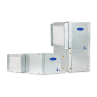
VERTICAL UNITS (50PCV)
Vertical units should be mounted level on a vibration absorbing
pad slightly larger than the unit base in order to minimize vibration
transmission from the unit to the building structure. See Fig. 7. It
is generally not necessary to anchor the unit unless required by lo-
cal code.
Fig. 7 — Mounting Vertical Units
All major service access for the vertical models is from the front
side of the unit. When installing the unit in a confined space such
as a closet, ensure that the service panel screws are accesible,
that the filter can be replaced without damage and that water and
electrical connections are accesible. For models with a unit-
mounted disconnect switch, make sure the switch can be easily
seen and operated.
To reduce sound transmission, units should be installed using flex-
ible electrical conduit and hose kits. Care should be taken to en-
sure that no part of the unit cabinet is touching part of the building
structure. For ducted return applications, a flexible duct connec-
tion should be used. Mount the unit on a vibration absorption pad
slightly larger than the entire base to minimize vibration transmis-
sion. It is not necessary to mount the unit on the floor.
Step 5 — Check Duct System
All units are provided with a return air duct flange and supply air
duct connections. Refer to unit dimensional drawings (Fig. 1 and
2) for physical dimensions of the collar and flange.
A flexible connector is recommended for supply and return air
duct connections on metal duct systems. All metal ducting
should be insulated with a minimum of 1 in. duct insulation to
avoid heat loss or gain and prevent condensate from forming
during the cooling operation. Application of the unit to uninsu-
lated ductwork is not recommended as the unit’s performance
will be adversely affected.
If the unit will be installed in a new installation with new
ductwork, the installation should be designed using current
ASHRAE (American Society of Heating, Refrigerating, and Air-
Conditioning Engineers) procedures for duct sizing. If the unit will
be connected to an existing duct system, a check should be made
to assure that the duct system has the capacity to handle the air re-
quired for the unit application. If the duct system is too small, larg-
er ductwork must be installed. Be certain to check for existing
leaks and repair. The duct system and all diffusers should be sized
to handle the designed airflow quietly. To maximize sound attenu-
ation of the unit blower, the supply and return air plenums should
be insulated. There should be no direct straight air path through
the air grille into the heat pump. The return air inlet to the heat
pump must have at least one 90-degree turn away from the space
return air grille. If air noise or excessive airflow are a problem, the
blower speed can be changed to a lower speed to reduce airflow.
(Refer to motor speeds and settings in Tables 8 and 9 on page 26.)
HORIZONTAL SUPPLY AIR CONFIGURATION CONVER-
SION
The supply air location on horizontal units can be quickly field
converted from end blow to straight through or vice-versa. To con-
vert the supply air direction, follow the steps below:
1. If connected to power, shut off the unit and disconnect switch
or circuit breaker.
2. Unscrew and remove the blower access panel.
3. Disconnect the wires from the unit electrical box to the
blower motor. Note which speed taps are wired for units with
PSC or constant torque motors.
4. Unscrew and carefully remove the blower panel with the
blower and motor attached. Be careful not to damage the
refrigerant coils or any other internal unit components.
5. Remove the blower support brackets from the bottom of the
blower housing and relocate them to the top of the blower
housing.
IMPORTANT: Units larger than six tons include an integral
angle iron frame with mounting holes present.
CAUTION
If the unit is located in a crawl space, the bottom of the unit
must be at least 4-in. above grade to prevent flooding of the
electrical parts due to heavy rains.
CAUTION
Do not connect discharge ducts directly to the blower outlet.
The factory filter rack should be left in place on a free return
system.
 Loading...