EasyManua.ls Logo

Carrier Aquazone 50PTH024 - User Manual

Carrier Aquazone 50PTH024
68 pages
Print Icon
To Next Page IconTo Next Page
Loading...
Manufacturer reserves the right to discontinue, or change at any time, specifications or designs without notice and without incurring obligations.
Catalog No. 04-53500146-01 Printed in U.S.A. Form 50PT-6SI Pg 1 6-22 Replaces: 50PT-5SI
Installation, Start-Up, and
Service Instructions
CONTENTS
Page
SAFETY CONSIDERATIONS . . . . . . . . . . . . . . . . . . . 2
GENERAL . . . . . . . . . . . . . . . . . . . . . . . . . . . . . . . . . . . 2
PRE-INSTALLATION . . . . . . . . . . . . . . . . . . . . . . . . . . 2
•INSPECTION
STORAGE
INSTALLATION . . . . . . . . . . . . . . . . . . . . . . . . . . . . . . 2
Step 1 — Check Jobsite . . . . . . . . . . . . . . . . . . . . . . . 2
HORIZONTAL UNITS (50PTH)
VERTICAL UNITS (50PTV)
INSTALLATION GUIDELINES (ALL UNITS)
Step 2 — Check Unit . . . . . . . . . . . . . . . . . . . . . . . . . . 4
•INSPECT UNIT
Step 3 — Locate Unit . . . . . . . . . . . . . . . . . . . . . . . . 10
•PROTECTION
Step 4 — Mount the Unit . . . . . . . . . . . . . . . . . . . . . . 10
DUCT FLANGES
HORIZONTAL UNITS (50PTH)
VERTICAL UNITS (50PTV)
Step 5 — Check Duct System . . . . . . . . . . . . . . . . . 11
HORIZONTAL SUPPLY AIR CONFIGURATION
CONVERSION
Step 6 — Install Condensate Drain . . . . . . . . . . . . . 11
Step 7 — Pipe Connections . . . . . . . . . . . . . . . . . . . 12
WATER LOOP APPLICATIONS
GROUND-WATER APPLICATIONS
GROUND-LOOP APPLICATIONS
INSTALLATION OF SUPPLY AND RETURN HOSE KIT
Step 8 — Wire Field Power Supply . . . . . . . . . . . . . 15
Step 9 — Wire Control Connections . . . . . . . . . . . . 33
COMPLETE C AND DELUXE D CONTROL
ECM INTERFACE THERMOSTAT CONNECTIONS
THERMOSTAT AND DDC SENSORS
AUXILIARY RELAY (DELUXE D ONLY)
ENERGY MANAGEMENT SWITCH (DELUXE D
ONLY)
BOILERLESS HEAT CONTROL (DELUXE D ONLY)
ALARM OUTPUT (ALL UNITS)
WSHP OPEN CONTROL
CONTROL TRANSFORMER
Step 10 — Configure Unit Control Components . . 34
UNIT PROTECTION MODULE (UPM)
PRE-START-UP . . . . . . . . . . . . . . . . . . . . . . . . . . . . . 35
System Checkout . . . . . . . . . . . . . . . . . . . . . . . . . . . 35
•CLEAN AIR COIL
Set Blower Motor Speed . . . . . . . . . . . . . . . . . . . . . . 36
CONSTANT TORQUE (ECM) MOTOR
CONSTANT AIRFLOW (ECM) MOTOR
System Flushing and Filling . . . . . . . . . . . . . . . . . . .39
System Flow . . . . . . . . . . . . . . . . . . . . . . . . . . . . . . . .39
FLOW VERIFICATION
FLOW REGULATION
ANTIFREEZE
START-UP . . . . . . . . . . . . . . . . . . . . . . . . . . . . . . . . . .40
Operating Limits . . . . . . . . . . . . . . . . . . . . . . . . . . . .40
ENVIRONMENT
POWER SUPPLY
UNIT STARTING CONDITIONS
Start-Up Procedure . . . . . . . . . . . . . . . . . . . . . . . . . .41
SCROLL COMPRESSOR ROTATION
COOLING MODE START-UP
HEATING MODE START-UP
OPERATION . . . . . . . . . . . . . . . . . . . . . . . . . . . . . . . .47
Power Up Mode . . . . . . . . . . . . . . . . . . . . . . . . . . . . .47
Unit Protection Module (UPM) . . . . . . . . . . . . . . . . .47
Units with Complete C or Deluxe D Controls . . . . . 47
STANDBY
COOLING
HOT GAS REHEAT (OPTIONAL FOR COMPLETE C OR
DELUXE D CONTROLS)
TWO WAY WATER FLOW CONTROL VALVE
(OPTIONAL)
BOILERLESS HEAT (DELUXE D ONLY)
PUMP/VALVE RELAY (DELUXE D ONLY)
Units with WSHP Open Controls . . . . . . . . . . . . . . .47
COOLING
REVERSE CYCLE HEATING
TWO POSITION OA DAMPER
MODULATING OA DAMPER WITH DCV
AUXILIARY MODULATING HOT WATER/STEAM
HEATING REHEAT
2-POSITION HOT WATER/STEAM HEATING REHEAT
SINGLE STAGE ELECTRIC AUXILIARY HEAT
AUTOMATIC FAN SPEED CONTROL
FAN SPEED CONTROL - DURING HEATING
FAN SPEED CONTROL - DURING COOLING
MODULATING WATER ECONOMIZER CONTROL
2-POSITION WATER ECONOMIZER CONTROL
POWER FAIL RESTART DELAY
SUPPLY AIR TEMPERATURE MONITORING/
CONTROL/ALARM
DEHUMIDIFICATION
SPACE TEMPERATURE ALARMS
CONDENSER WATER TEMPERATURE
MONITORING/ CONTROL/ALARM
HIGH CONDENSATE/OVERFLOW ALARM
FILTER STATUS ALARM
COMPRESSOR FAULT/LOCKOUT ALARM
INSUFFICIENT VENTILATION ALARM
RELATIVE HUMIDITY ALARM
TIME SCHEDULES
Aquazone
50PTH, PTV024-070
Two-Stage Water Source Heat Pumps
with Puron
®
Refrigerant (R-410A)

Table of Contents

Question and Answer IconNeed help?

Do you have a question about the Carrier Aquazone 50PTH024 and is the answer not in the manual?

Overview

The provided document is an installation, start-up, and service manual for the Aquazone™ 50PTH, PTV 024-070 Two-Stage Water Source Heat Pumps with Puron® Refrigerant (R-410A).

Here's a description of the device based on the manual:

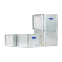
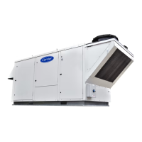
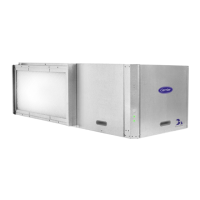
The Aquazone™ 50PTH, PTV 024-070 units are two-stage water source heat pumps designed for indoor installation. They utilize Puron® (R-410A) refrigerant and are equipped with an Electronic Commutated Motor (ECM) for constant airflow. These units are designed to provide both cooling and heating functions, with advanced control features for optimal performance and energy efficiency.

Function Description:

The heat pump operates in two primary modes: cooling and heating. In cooling mode, it uses a two-stage compression system to maintain the desired cooling setpoint. To enhance dehumidification and reduce noise, the fan operates at the lowest possible speed, increasing as needed to meet load conditions or if the supply air temperature (SAT) approaches the minimum SAT limit (50°F default). If the SAT continues to fall 5 degrees below the minimum limit, all cooling stages are disabled. The reversing valve remains in the cooling position until the opposite mode is required.

In heating mode, the unit also uses two-stage compression to maintain the desired heating setpoint. Similar to cooling, the fan operates at the lowest speed, increasing if the SAT approaches the maximum SAT limit (110°F default). If the SAT continues to rise 5°F above the maximum limit, all heating stages are disabled. The reversing valve remains in the heating position until the opposite mode is required.

Optional features include hot gas reheat for dehumidification, a two-way water flow control valve, and boilerless heat functionality. The hot gas reheat activates cooling and the hot gas reheat outputs when space humidity exceeds the setpoint and the unit is not actively heating or cooling, operating the fan at medium speed. The two-way water flow control valve regulates water flow through the unit during cooling, heating, or dehumidification calls and is disabled otherwise. Boilerless heat, available with Deluxe D controls, disables the compressor and enables auxiliary heat when the entering water temperature falls below a setpoint, and vice-versa. A pump/valve relay is also available to enable/disable field-installed flow control valves or circulator pumps during cooling, heating, or dehumidification.

Important Technical Specifications:

The units are available in various sizes (024-070) with different physical dimensions, electrical characteristics, and performance data. For instance, a 50PTH 024 unit has a width of 25.1 inches, depth of 64.1 inches, and height of 19.7 inches. Electrical specifications vary by model and phase (single or three-phase), with supply voltages typically 208/230V or 460V. Control voltage is 24 VAC. Water flow rates are between 1.5 and 3.0 GPM per nominal cooling ton. The refrigerant used is Puron® (R-410A).

The Unit Protection Module (UPM) monitors safeties such as high-pressure switch, low-pressure switch, water-side freeze protection sensor (default trip at 26°F, adjustable to 15°F), air coil freeze protection sensor (default trip at 26°F), and condensate overflow protection sensor. The UPM also incorporates anti-short cycle timers (5-minute delay on break), random start delays (270-300 seconds), low-pressure bypass timers (120 seconds), and brownout/surge protection (shuts down if voltage falls below 18 VAC).

Usage Features:

  • Control Systems: Units can be controlled using included thermostat inputs (R, O, Y1, C, G) for single-stage heat pump thermostats or field-installed DDC (Direct Digital Controls). WSHP Open controls offer advanced functionality like automatic fan speed control and intelligent alarming.
  • Fan Speed Control: The ECM allows for up to three fan speeds, optimizing for quiet operation and efficiency. Fan speed adjusts based on load conditions and supply air temperature limits.
  • Economizer Control: Modulating or two-position water economizer control is available to utilize the water loop for cooling or heating when water loop temperatures are suitable, reducing compressor operation.
  • Supply Air Temperature Monitoring: The control monitors SAT and has configurable limits for high and low SAT alarms, adjusting fan speed and compressor stages to maintain desired temperatures.
  • Dehumidification: With hot gas reheat, the unit can actively dehumidify when space humidity exceeds the setpoint and the unit is not in active heating or cooling.
  • Time Schedules: Onboard time clock and configurable schedules for occupancy, holidays, and overrides are available.
  • Start-up Procedure: A detailed start-up checklist is provided, including steps for verifying voltage, wiring, water connections, pump operation, filter installation, fan operation, compressor rotation (for 3-phase scroll compressors), and checking unit voltages and control voltages.
  • Troubleshooting: A comprehensive troubleshooting guide is included, detailing possible causes and solutions for various faults indicated by the UPM's LED blink codes (e.g., high pressure, low pressure, freeze fault, condensate fault, brownout fault).

Maintenance Features:

  • Periodic Checkups: An annual checkup by a licensed refrigeration mechanic is recommended, including recording performance measurements (volts, amps, water temperature differences).
  • Filter Maintenance: Filters require regular changes or cleanings, with frequency depending on the environment (e.g., every 60 days for single-family homes, biweekly for motels).
  • Condensate Drain Pans: Quarterly checks, cleaning, and flushing are recommended to ensure proper drainage.
  • Refrigerant System: Verify air and water flow rates, check superheat and subcooling ranges (Tables 14-23), and recover/reweigh refrigerant if necessary. Puron® (R-410A) requires specific tools and procedures due to higher pressures and the use of POE oil.
  • Compressor: Annual amperage checks to ensure amp draw is within 10% of serial plate data.
  • Fan Motors: Fan motors are lubricated and do not require periodic oiling unless dry operation is suspected. Annual dry operation and amperage checks are recommended.
  • Air Coil Cleaning: Clean evaporator coils as required by condition, using a 10% solution of dishwasher detergent and water, followed by rinsing.
  • Condenser Cleaning: Water-cooled condensers may require cleaning of scale annually or more often if water is contaminated. Proper water treatment is crucial.
  • Refrigerant Charging: Units are shipped with a full operating charge. Recharging involves specific steps, including using a digital thermometer and pressure gauge, and comparing subcooling temperature to normal values. Overcharging should be avoided to prevent compressor flooding.

Carrier Aquazone 50PTH024 Specifications

General IconGeneral
BrandCarrier
ModelAquazone 50PTH024
CategoryHeat Pump
LanguageEnglish

Related product manuals