Type B Electronic Control
GB - 2
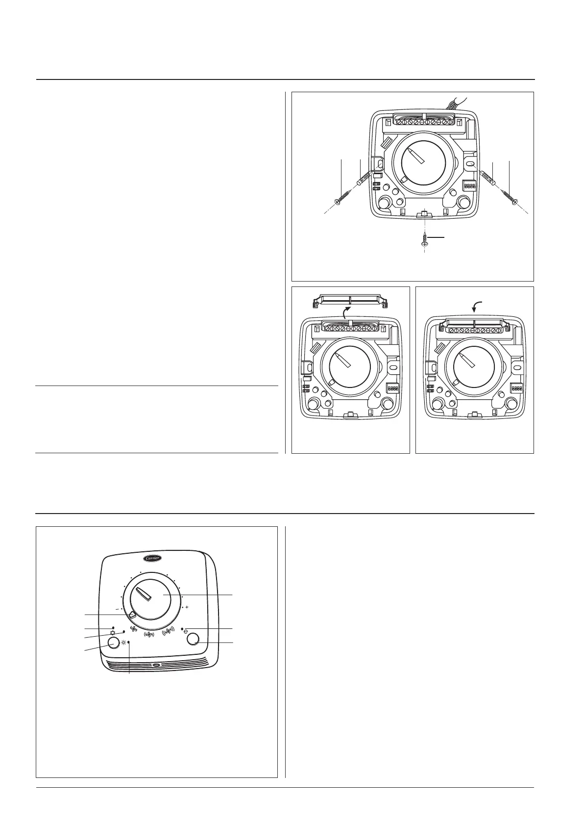
Fig. 5
ON/OFF/fan speed selector
Blue LED - cooling operation
Seasonal changeover button
Red LED - heating operation
Energy saving button
Yellow LED - energy saving operation
Temperature knob
Automatic seasonal changeover
Type “B” control is used in 4-pipe systems and 2-pipe systems with
electric heater.
Functions
Control "B" have a knob to select the temperature, with a range
from 10°C to 30°C, and room temperature is maintained at the
selected value.
Fan operation
With the fan speed selector fan mode can be set either manually
or automatically.
In the manual mode it is possible to select three fan speeds (low/
medium/high) according to personal preference.
In the auto mode fan speed is regulated by a microprocessor in the
control in relation to the temperature chosen.
During installation, it is possible to select continuous fan operation
via the switch located on the electronic board (see paragraph “Dip-
switch confi guration”).
In the heating mode, the fan operation is delayed by approximately
one minute to allow the residual heat on the heat exchanger coil or
the electric heater (if any) to be released.
20°c
O
FF
AUTO
A
Wall-mounted control
• Remove the control cover, unscrewing the screw located in the
bottom part (Fig. 2). Secure the control to the wall, marking the
drill holes.
• Drill the holes previously marked.
Avoid drilling with the control already placed on wall.
• Prepare electrical connections between the control terminal block and
the unit control box panel as shown in the wiring diagram in fi g. 9.
For the specifi c connection between the control and the fan coil
unit refer to the diagram shown on the unit.
• Remove the cable protection guard and carry out the connec-
tions to the control terminal block (Fig. 3).
The connecting cable of the fan coil unit and the accessory cables
should be of the H07 RN-F type (or higher) according to EN
60335-2-40 standard.
All electric connection cables should be at least 1,5 mm.
The maximum connecting distance between unit and control
should not exceed 15 metres.
• After connections to the terminal block have been made, replace
the cable protection guard as shown in the fi gure (Fig. 4).
• Fix the control to the wall using the corresponding screw anchors .
• Put the control cover back to its place by reinstalling the screw
previously removed
(Fig. 2).
IMPORTANT:
• All connections between the unit and the control must be
placed into a proper plastic conduit.
• Handle the control with extreme care. Do not touch electronic
components to avoid damaging them.
Fig. 2
Screw
Screw anchor
Screw to close the control
Assembly
CONTROL TYPE "B"
Control
Fig. 3 Fig. 4

 Loading...