GB - 3
Type B Electronic Control
ENGLISH
Frost - protection
This function keeps the temperature from dropping below 7°C in
rooms not used for long periods of time.
When this temperature is reached, the control activates the valve
and puts the fan on high speed.
The frost protection function can be activated through the associ-
ated micro-switch (see dip switch confi guration); if enabled, this
function activates even when the control is in the OFF position.
Energy saving
This function is especially useful when air conditioning at night or
in rooms where the user is likely to be absent for a longer period of
time.
In this case, pushing button
raises the temperature during cooling
by 4°C and lowers it during heating by 4°C.
Enabling this function (yellow LED ON) cuts out other displays.
During energy saving, even the brightness of the yellow LED is
dimmed.
Seasonal changeover
Manual
Selection of heating/cooling is done manually by pushing the button
on the control.
Automatic
The automatic seasonal changeover allows automatic switching of
the fan coil operating mode to cooling or heating, depending on the
temperature set by the user and on the room temperature.
External contact
The control has an input that can be used as window contact or
presence detection.
When such a signal is activated (presence of line voltage on the
terminal block contact) the control is set to OFF mode.
As a consequence, all outputs (fan, valves etc.) are disconnected,
and only the frost protection is active, if switched ON by the ap-
propriate dip-switch.
Additional heating
This function allows the water soilenoid valve and the electric hea-
ters to work simultaneously.
With this function activated by the dip switch (no. 5) – see section
microswitch confi guration (dip switch) – the function is active.
To avoid overheating due to simultaneous operation of water and
heating elements, the temperature of the incoming water of the coil
is adjusted by a special sensor (optional) that must be positioned
on the inlet pipe.
If the function is active but the sensor is not connected, the control
enters the alarm mode, the red led fl ashes and all the user devices
are switched off.
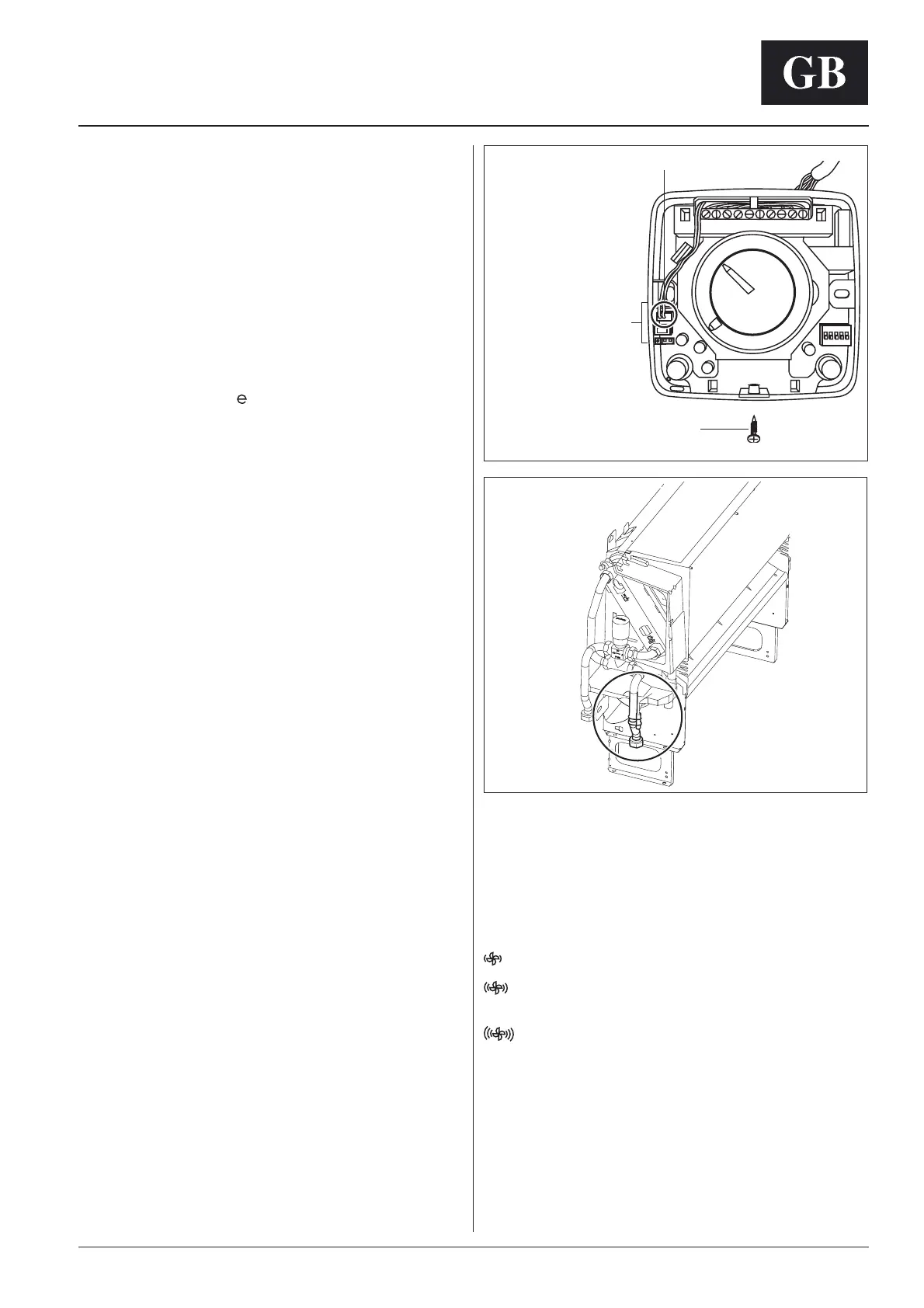
Sensor installation:
Open the control by loosening the screw used to close the con-
trol (see fi g. 6).
Connect the sensor on the connector side of the electronic board to
connector
(see fi g. 6).
Connect the other end to the inlet water pipe using the clip and the
strips supplied (see fi g. 7) .
Complete by insulating the pipe with the insulating tape supplied.
Control
Use:
ON/OFF/fan speed selector
OFF In this position the control is OFF and all functions are disa-
bled.
If the frost protection function is selected by the dip-switch,
this is activated even if the control is in OFF position.
With selector in this position, the fan operates at low speed.
With selector in this position, the fan operates at medium
speed.
With selector in this position, the fan operates at high
speed.
AUTO The control maintains the selected temperature, acting
automatically on the fan speed.
Temperature selector
Its purpose is to maintain the temperature at the desired level.The
reference value at the centre of the range is 20°C .
By turning the knob towards the symbol ( – ) the temperature is
reduced from the original setting (minimum value is 10°C).
By turning the knob towards the symbol ( + ), the temperature is
raised from the original setting (maximum value is 30°C).
Fig. 7
Screw to close the control
Water temperature sensor
Fig. 6
X1 : Water probe (optional)
X2 : Air probe
X3 : Jumper for enabling
the probe on air inlet

 Loading...