Type B Electronic Control
GB - 4
Control
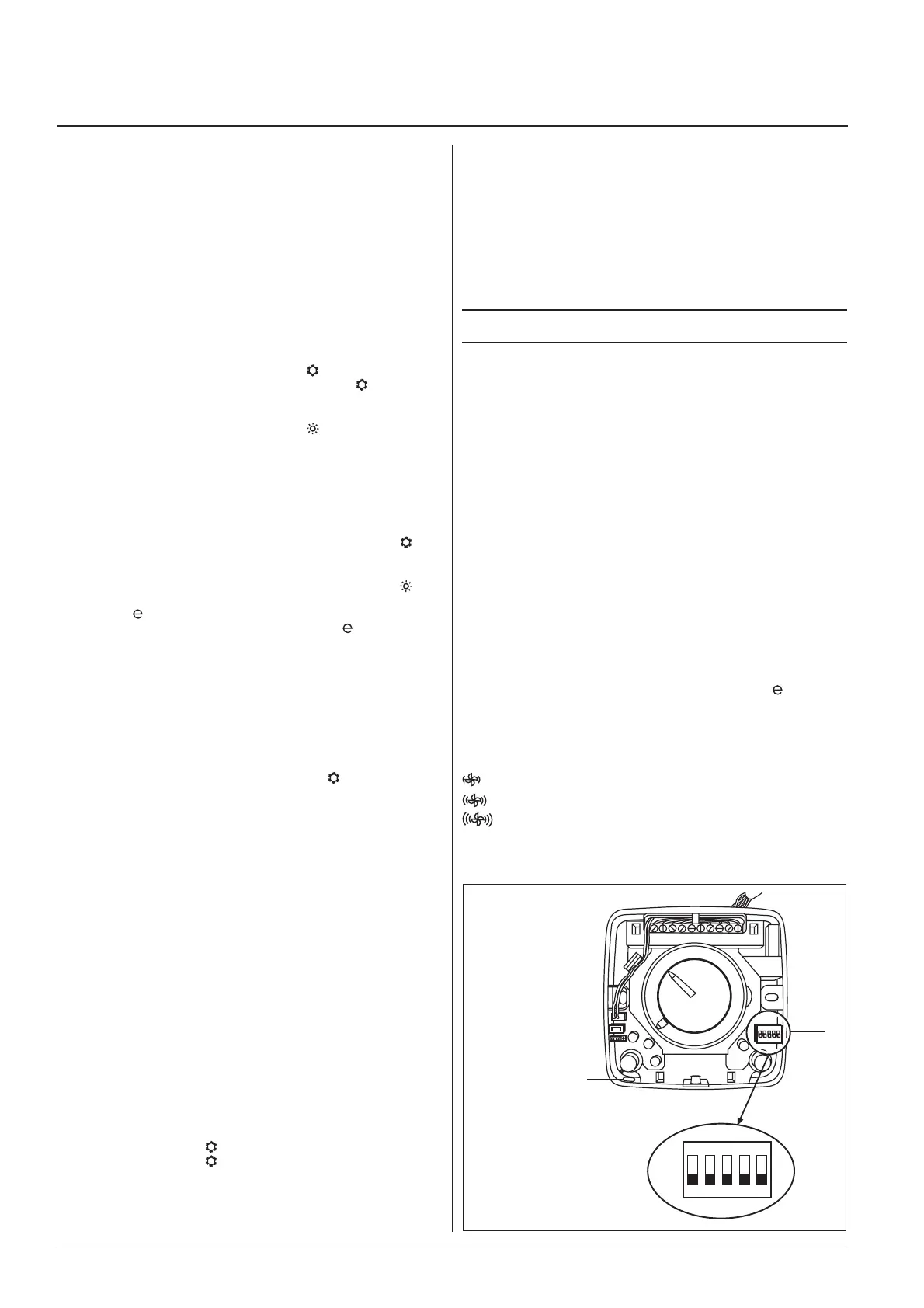
ON
1 2 3 4 5
OFF
Seasonal changeover button
This button allows selecting the operating mode, cooling, heating or
automatic.
Energy saving button
This button activates the energy saving function which modifi es room
temperature as follows: in heating, the selected temperature is redu-
ced by 4°C; in cooling, the selected temperature is raised by 4°C.
Light indicators
Blue LED
ON cooling mode (
).
Flashing frost protection mode (
).
Red LED
ON heating mode (
).
Flashing Presence of a fault
(sensor failed or not connected).
Yellow LED (A)
ON automatic mode (A).
Blue LED + Yellow LED
Both ON automatic mode (A) - cooling (
).
Red LED + Yellow LED
Both ON automatic mode (A) - heating (
).
Yellow LED (
)
ON energy saving mode
.
Flashing External contact is open.
Red / Blue LED
Flashing “Autotest” mode.
Dip-switch functions (Microswitch)
Dip-switch No. 1
When ON permits enabling the frost protection (
) function.
Dip-switch No. 2
When ON permits fan operation at the selected speed even if the
set point is satisfi ed.
Dip-switch No. 3
When ON restricts the range of temperature selection, according to
the following limits:
Cooling: minimum selectable temperature: 23°C.
Heating: maximum selectable temperature: 21°C.
Dip-switch No. 4
When ON periodically activates the fan even if the set point is sati-
sfi ed (air sampling).
Dip-switch No. 5
When ON permits enabling the Booster Heating function (additio-
nal heating)
Dip-Switch confi gurations (Microswitch)
Dip-switch 1
OFF Frost protection (
) disabled.
ON Frost protection (
) enabled.
Dip-switch 2
OFF Ventilation controlled by thermostat.
ON Continuous ventilation.
Fig. 8
Internal temperature sensor
Dip-switch selector
Dip-switch 3
OFF Temperature block disabled.
ON Temperature block enabled.
Dip-switch 4
OFF Air sampling disabled.
ON “Air sampling enabled.
Dip-switch 5
OFF “Booster Heating” disattivato.
ON “Booster Heating” attivato.
NOTE:
Factory setting is with all dip-switches in the OFF position.
Diagnostic warnings
The following alarm situations are indicated:
Defective sensors: the red LED fl ashes.
Possible causes:
• failure or short circuit of internal sensor;
• failure or short circuit of water temperature sensor.
Incorrect confi guration
The yellow LED fl ashes every 0.25 seconds.
This happens when:
• in control, both centralised seasonal changeover signals “RC and
RH” are enabled.
Autotest
The autotest function is activated by holding the seasonal changeo-
ver button pressed and at the same time pressing the “
” button
three times within 1 second. In this way it is possible to check the
starting of all fan coils.
The blue and red LEDs will begin to fl ash.
Each of the various units will be activated for 10 seconds in the
following sequence:
Low fan speed.
Medium fan speed.
High fan speed.
CV Motorized cold-water valve.
HV Motorized hot-water valve.

 Loading...