PROCEDURE 2—BOILER LOCATED IN CONFINED SPACE
EXAMPLE 2A: ALL AIR FROM INSIDE THE BUILDING
The confined space shall be provided with two permanent openings communicating directly with an additional room(s) of sufficient volume so
that the combined volume of all spaces meets the criteria for an unconfined space. The total input of all gas utilization equipment installed in the
combined space shall be considered in making this determination. Each opening shall have a minimum free area of one square inch per 1,000 Btu
per hour of the total input rating of all gas utilization equipment in the confined space, but not less than 100 square inches. One opening shall be
within 12 inches of top and one within 12 inches of bottom of enclosure. The minimum dimension of air openings shall not be less than 3 inches.
EXAMPLE 2B: ALL AIR FROM OUTDOORS
The confined space shall communicate with the outdoors in accordance with examples 1 or 2. The minimum dimension of air openings shall not
be less than 3 in. Where ducts are used, they shall be of the same cross-sectional area as the free area of the openings to which they connect.
1. Two permanent openings, one commencing within 12 inches of top, and one commencing within 12 inches of bottom of enclosure shall
be provided. The openings shall communicate directly, or by ducts, with the outdoors or spaces (crawl or attic) that freely communicate
with the outdoors
a. Where directly communicating with the outdoors or where communicating to the outdoors through vertical ducts, each opening shall have
a minimum free area of 1 sq. in. per 4000 Btu per hour of total input rating of all equipment in enclosure. (See Table 3A.)
b. Where communicating with the outdoors through horizontal ducts, each opening shall have a minimum free area of 1 sq. in. per 2000
Btu per hour of total input rating of all equipment in enclosure. (See Table 3B.)
2. One permanent opening commencing with 12 inches of top of enclosure shall be permitted where equipment has clearance of at least 1 inch
from sides and back and 6 inches from front of appliance. The opening shall directly communicate with the outdoors or shall communicate
through a vertical or horizontal duct to the outdoors or spaces (crawl or attic) that freely communicate with the outdoors and shall have a
minimum free area of:
a. 1 sq. inch per 3000 Btu per hour of total input of all equipment located in enclosure (see Table 3C), and
b. Not less than the sum of the areas of all vent connectors in the confined space.
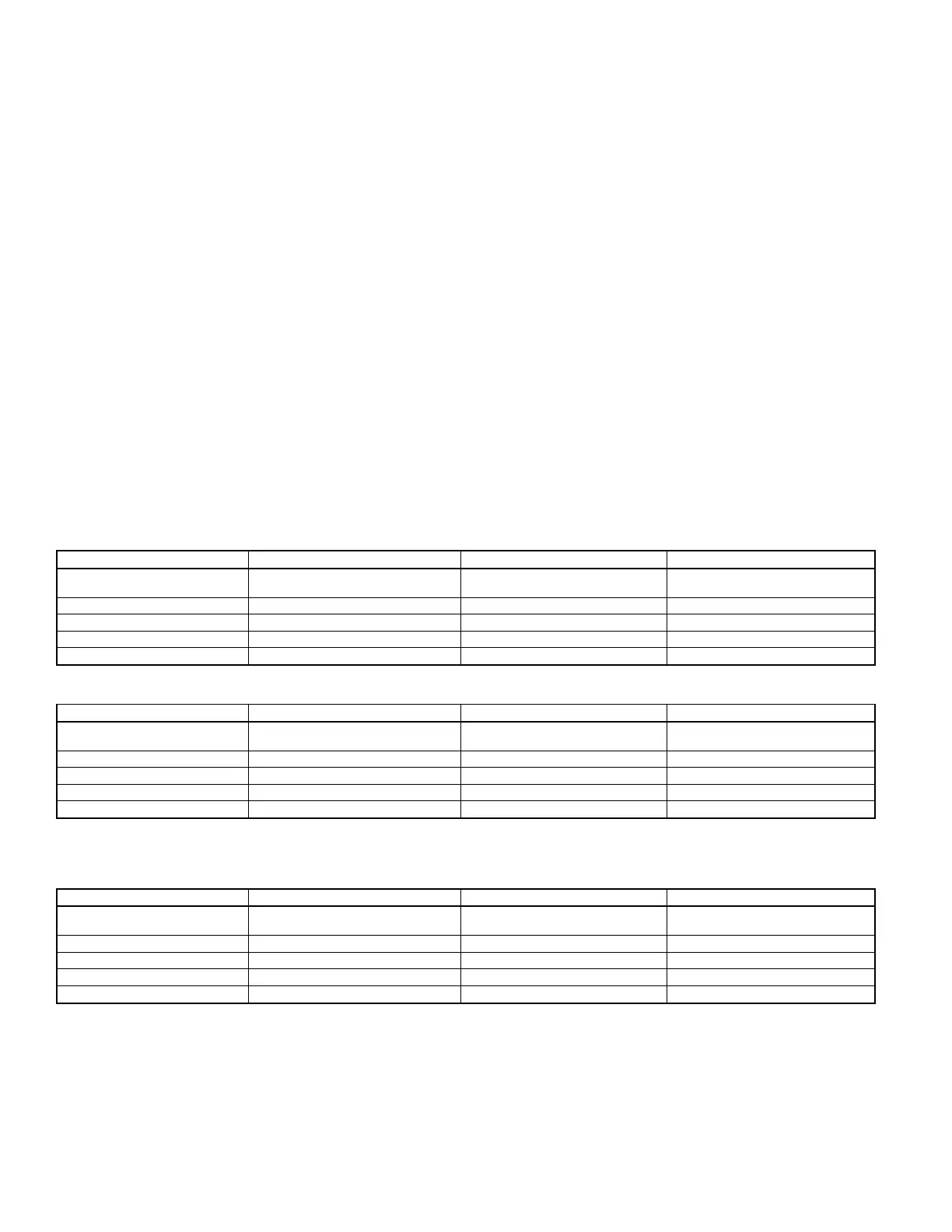
Table 3A—Fresh Air Duct Capacities for Vertical Ducts (Btuh)*
100% FREE AREA 75% FREE AREA 25% FREE AREA
Fresh Air
Duct Size (In.)
1/4-in. Mesh
Screen
Metal
Louvers
Wood
Louvers
3" X 12" 144,000 108,000 36,000
8"X8" 256,000 192,000 64,000
8" X 12" 384,000 288,000 96,000
8-1/2" X 16" 512,000 384,000 128,000
* 1 Square Inch per 4,000 Btuh
Table 3B—Fresh Air Duct Capacities for Horizontal Ducts (Btuh)*
100% FREE AREA 75% FREE AREA 25% FREE AREA
Fresh Air
Duct Size (In.)
1/4-in. Mesh
Screen
Metal
Louvers
Wood
Louvers
3" X 12" 72,000 54,000 18,000
8"X8" 128,000 96,000 32,000
8" X 12" 192,000 144,000 48,000
8-1/2" X 16" 256,000 192,000 64,000
* 1 Square Inch per 2,000 Btuh
Table 3C—Fresh Air Duct Capacities for Vertical or Horizontal Ducts (Btuh)*
100% FREE AREA 75% FREE AREA 25% FREE AREA
Fresh Air
Duct Size (In.)
1/4-in. Mesh
Screen
Metal
Louvers
Wood
Louvers
3" X 12" 108,000 81,000 27,000
8"X8" 192,000 144,000 48,000
8" X 12" 288,000 216,000 72,000
8-1/2" X 16" 384,000 288,000 96,000
* 1 Square Inch per 3,000 Btuh
INSTALLATION—SYSTEM PIPING
The near boiler piping (piping around boiler) must be considered as part of boiler for proper water level control and to produce dry steam. Correct
near boiler piping is crucial to proper operation of boiler and heating system. Follow these recommendations carefully.
1. Place boiler in selected location as near chimney as possible.
2. Install relief valve using factory-supplied 3/4-in. coupling into 3/4-in. pipe nipple on top of boiler. Make a discharge pipe using 3/4-in. pipe
(field supplied) to carry water or steam to a nearby drain. Do not connect discharge pipe directly to drain but leave an air gap. The
downstream end of discharge pipe must be unthreaded. No shutoff of any description shall be placed between relief valve and boiler, or
on discharge pipes between such safety valves and the atmosphere. Installation of relief valve shall conform to requirements of the
ANSI/ASME Boiler and Pressure Vessel Code, Section IV. The manufacturer is not responsible for any water damage.
—6—

 Loading...