CONTROL PADS ON THE DEHUMIDIFIER
IDENTIFICATION OF PARTS
15
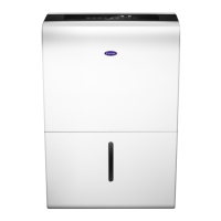
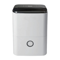
Identication of parts
Front
1
Control panel
2
Handle (both sides)
3
Air outlet grille
4
Water bucket
5
Water level window
5
4
2
3
Fig. 2
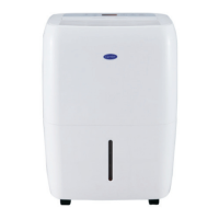
Rear
1
Drain hose outlet
2
Caster
3
Power Cord and plug
4
Air intake grille
5
Air lter (behind the grill)
6
HEPA lter(supplied with unit, install as shown Fig.B)
7
Power cord Buckle(Used only when storing the unit.)
1
2
5
4
6
7
Fig. 3
NOTE: All the pictures in the manual are for explanation
purposes only. The actual shape of the unityou purchased
may be slightly different, the actual shape shall prevail. The
operations and functions are the same.
Fig B
Hepa lter
Air intake grill
IDENTIFICATION OF PARTS
 Loading...