EasyManua.ls Logo

Carrier Crystal Plus 38KHFT12-708 User Manual

Carrier Crystal Plus 38KHFT12-708
58 pages
To Next Page IconTo Next Page
Page #1 background imageLoading...
Page #1 background image
Rev. (0) - 2012
Quality
Management System
ISO 9001 : 2008
Certicate No.: QS-5519HH
Enviromental
Management System
ISO 14001 : 2004
Certicate No : 12 104 30334 TMS
Safety
Management System
BS OHSAS 18001 : 2007
Certicate No : 12 116 30334 TMS
220-240V ~, 50Hz
R
2
2
03502821
Carrier is committed to continuously improving its products according to national and international standards
to ensure the highest quality and reliability standards, and to meet market regulations and requirements.
All specications subject to change without prior notice according to Carrier policy of continuous development.
INSTALLATION MANUAL
Hi Wall Split Air Conditioners
53KHET 12-18-24 Cool Only
53QHET 12-18-24 Heat Pump
Question and Answer IconNeed help?

Do you have a question about the Carrier Crystal Plus 38KHFT12-708 and is the answer not in the manual?

Carrier Crystal Plus 38KHFT12-708 Specifications

General IconGeneral
TypeSplit AC
Cooling Capacity1 Ton
Compressor TypeRotary
RefrigerantR32
Outdoor Noise Level52 dB
Star Rating3 Star
Indoor Unit Weight9 kg
Power Supply230V, 50Hz
Outdoor Unit Dimensions (H x W x D)550 x 700 x 275 mm
Noise Level (Indoor)37 dB

Summary

GENERAL NOTES TO INSTALLER

PRECAUTIONS BEFORE INSTALLATION

SAFETY PRECAUTIONS

Critical safety measures to follow prior to commencing installation work.

Warranty Exclusions

Details of conditions not covered by the product warranty.

SPLIT SYSTEM DESCRIPTION

12K-18K Models Overview

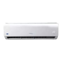
Description of split system models for 12K and 18K capacities.

24K Model Overview

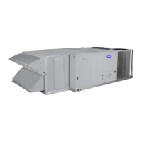
Description of the split system model for 24K capacity.

MODELS

Heat Pump Models

Model designations and specifications for Heat Pump systems.

Cool Only Models

Model designations and specifications for Cool Only systems.

OPERATING LIMITS

Cooling Operating Limits

Temperature limits and conditions for cooling operation.

Heating Operating Limits

Temperature limits and conditions for heating operation.

Main Power Supply Specifications

Electrical specifications for the main power supply.

INDOOR UNIT DIMENSIONS AND WEIGHT

OUTDOOR UNIT DIMENSIONS AND WEIGHT

INDOOR UNIT INSTALLATION LOCATION

8.1 LOCATION SELECTION CONSIDERATIONS

Guidelines for choosing the optimal indoor unit placement.

OUTDOOR UNIT INSTALLATION LOCATION

9.1 INSTALLATION LOCATIONS

General guidance on where outdoor units can be installed.

9.2 LOCATION SELECTION CONSIDERATIONS

Detailed factors for selecting the best outdoor unit location.

9.3 MINIMUM CLEARANCES FOR SINGLE OUTDOOR UNIT

9.4 MINIMUM CLEARANCES FOR SERIAL OUTDOOR UNITS

INSTALLATION LOCATION CHECK LIST

Indoor Unit Checklist

Checklist items to verify the indoor unit installation.

Outdoor Unit Checklist

Checklist items to verify the outdoor unit installation.

Refrigerant Piping Checklist

Checklist items for verifying refrigerant piping installation.

INSTALLATION ACCESSORIES

11.1 STANDARD FACTORY ACCESSORIES

List of standard accessories provided with the unit.

11.2 EXPORT MARKET ACCESSORIES

List of standard accessories for export markets.

OTHER INSTALLATION ACCESSORIES

INSTALLATION CHART

INDOOR UNIT INSTALLATION

13-1 PREPARATION STEPS BEFORE INSTALLATION

Initial steps and considerations before installing the indoor unit.

INDOOR UNIT INSTALLATION STEPS

REMOTE CONTROL INSTALLATION

14-1 HOW TO INSERT BATTERIES

Instructions for installing batteries in the remote control.

USING WIRELESS REMOTE CONTROL

OUTDOOR UNIT INSTALLATION

15.1 PREPARATION STEPS BEFORE INSTALLATION

Steps to prepare the outdoor unit for installation.

15.2 WALL INSTALLATION STEPS

Detailed steps for mounting the outdoor unit on a wall.

CONNECTING REFRIGERANT PIPING LINES

16-1 REFRIGERANT CONNECTIONS CHART

Visual guide to refrigerant piping connection steps.

INDOOR UNIT PIPING OUTLET LOCATIONS

REFRIGERANT PIPING CONNECTION INSTRUCTIONS

REFRIGERANT PIPING LINES USAGE

Outdoor Unit Below Indoor Unit Piping

Guidelines for piping when the outdoor unit is below the indoor unit.

Outdoor Unit Above Indoor Unit Piping

Guidelines for piping when the outdoor unit is above the indoor unit.

Same Level Unit Piping

Guidelines for piping when units are on the same level.

REFRIGERANT PIPING DIAMETERS AND LENGTHS

REFRIGERANT CHARGE

OUTDOOR UNIT REFRIGERANT CONNECTIONS

INDOOR UNIT REFRIGERANT CONNECTIONS

REFRIGERANT PIPING CONNECTIONS DESCRIPTION

CUTTING AND FLARING TOOLS

REFRIGERANT PIPING PREPARATION STEPS

CONNECTING PIPING TO INDOOR UNIT

CONNECTING PIPING TO OUTDOOR UNIT

AIR PURGING OF PIPING LINES

16-14-1 INTRODUCTION TO AIR PURGING

Importance and effects of air purging in the refrigeration system.

16-14-2 AIR PURGING USING CONTAINED REFRIGERANT

Procedure for purging using onboard refrigerant.

AIR PURGING USING VACUUM PUMP

PUMPING DOWN (RE-INSTALLATION)

REFRIGERANT LEAK CHECK

INSULATING REFRIGERANT PIPING LINES

CONNECTING CONDENSATE DRAIN LINE

17-1 DRAIN LINE SIZE SPECIFICATIONS

Specifications for the condensate drain line size and material.

17-2 DRAIN LINE OUTLET LOCATIONS

Options for routing the drain line from the indoor unit.

DRAIN LINE CONNECTION INSTRUCTIONS

CONNECTING ELECTRICAL WIRING

18-1 WIRING: POWER SUPPLY TO CIRCUIT BREAKER

Wiring between the power source and the unit's circuit breaker.

WIRING: UNIT TO CIRCUIT BREAKER

ELECTRICAL DATA

OUTDOOR UNIT WIRING PREPARATION

HEAT PUMP SYSTEM WIRING

18-5-1 OUTDOOR UNIT WIRING (HEAT PUMP)

Wiring details for the outdoor unit of heat pump systems.

18-5-2 INDOOR UNIT WIRING (HEAT PUMP)

Wiring details for the indoor unit of heat pump systems.

FIELD ELECTRICAL WIRING

18-6-1 COOL ONLY WIRING (12K-18K)

Wiring diagram for cool-only systems (12K-18K).

18-6-2 HEAT PUMP WIRING (12K-18K)

Wiring diagram for heat pump systems (12K-18K).

FIELD WIRING (SIZE 24K)

FINISHING INSTALLATION STEPS

TEST RUNNING

20.1 PRECAUTIONS BEFORE TEST RUNNING

Safety and preparation steps before performing test runs.

20.2 COOLING TEST RUNNING (MANUAL BUTTON)

How to perform a cooling test using the manual control button.

COOLING TEST RUNNING STEPS

HEATING TEST RUNNING STEPS

AIR CIRCULATION FOR INDOOR UNIT

AIR FLOW DIRECTION CONTROL

Methods for controlling the direction of airflow from the indoor unit.

AIR DIRECTION FUNCTION

How the unit automatically adjusts vertical airflow direction.

SWING FUNCTION

How to use the automatic swing function for horizontal louvers.

AFTER INSTALLATION CHECK LIST

22.1 INDOOR UNIT CHECKLIST

Checklist items to verify the indoor unit installation.

22.2 OUTDOOR UNIT CHECKLIST

Checklist items to verify the outdoor unit installation.

22.3 REFRIGERANT PIPING CONNECTIONS CHECKLIST

Checklist items for refrigerant piping connections.

22.4 CONDENSATE DRAIN LINE CHECKLIST

Checklist items for condensate drain line connections.

22.5 ELECTRICAL CONNECTIONS CHECKLIST

Checklist items for electrical connections.

FINISHING INSTALLATION CHECKS

TESTING RUNNING CHECKS

CUSTOMER GUIDANCE

SELF DIAGNOSTIC FUNCTION FOR MALFUNCTIONS DETECTION

COOL ONLY SYSTEM MALFUNCTIONS

Malfunction codes and LED indicators for Cool Only models.

HEAT PUMP SYSTEM MALFUNCTIONS

Malfunction codes and LED indicators for Heat Pump models.

Related product manuals