- 16 - - 21 -
05-05-05
Micro No.
Position
MICROS BLOCK S1
1-3-4-5-6
OFF
2
ON
Micro No.
Position
MICROS BLOCK S2
2-4-5
OFF
1-3-6
ON
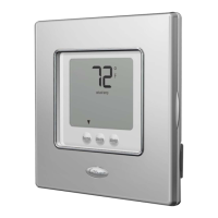
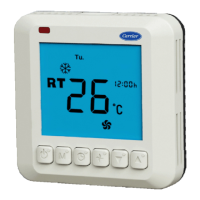
NON-PROGRAMMABLE THERMOSTAT
MODELS « 50HZ 016 » WITHOUT FREE-COOLING
REF.- ETN.05
Y 1 G W 1 C R
Y 1 G Y 2 S W 2 ESEW 1OCR
O72
THERMOSTAT TERMINALS
UNIT ELECTRICAL BOX TERMINALS
(Heat pump Models)
NOTE
Before connecting the
alarms, read pages 34 and
35 of this manual.
SEE
NOTE
This Unit can exceptionally be configured as Cooling only, despite it including a Heat
Pump.
CONNECTION DIAGRAMS
BETWEEN
THE THERMOSTAT AND THE UNIT
 Loading...