- 31 -- 6 -
4.- Electrical connections
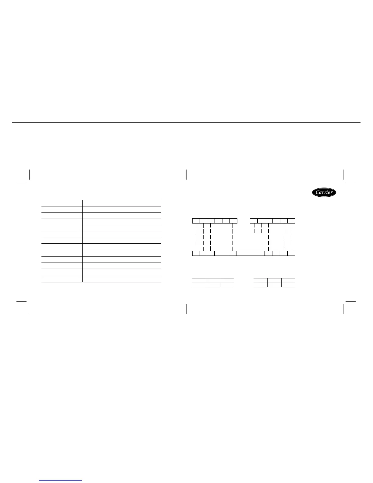
Indication of the meaning of the thermostat connections.
TERMINAL BLOCKS FUNCTION
R 24 Vac
C0 Vac
E Alarm (inlet for NA power-free contact
E Alarm (inlet for NA power-free contact)
O Reversible valve
W1 Electrical heater
W2 Electrical heater
S Atmospheric sensor or remote return
S Atmospheric sensor or remote return
Y2 Compressor 2 (Cold / Heat)
G Ventilation
Y1 Compressor 1 (Cold / Heat)
¡IMPORTANT! Before making any modification to the Micro-switches,
disconnect any power to the air conditioning unit.
10-06-05
Micro No.
Position
MICROS BLOCK S1
1-3-4-5-6
OFF
2
ON
Micro No.
Position
MICROS BLOCK S2 (*)
2-4-5
OFF
1-3-6
ON
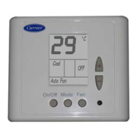
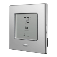
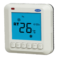
NON-PROGRAMMABLE THERMOSTAT
MODELS « 38XTZ + 40ABZ 016-024 »
THERMOSTAT TERMINALS
UNIT ELECTRICAL BOX TERMINALS
(Cooling only Models)
REF.- ETN.15
Y 1 G 7 2 C R
Y 1 G Y 2 S W 2 ESEW 1OCR
7 1
(
*
)
.- Set Micro no 5 on
Block S2 to ON when the
Unit starts up the Hot Water
Coil.
Y 2
NOTE
Before connecting the
alarms, read pages 34 and
35 of this manual.
SEE
NOTE




 To Next Page