- 32 - - 5 -
10-06-05
Micro No.
Position
MICROS BLOCK S1
1-3-4-5-6
OFF
2
ON
Micro No.
Position
MICROS BLOCK S2
2
OFF
1-3-4-5-6
ON
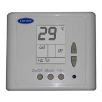
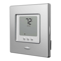
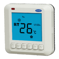
NON-PROGRAMMABLE THERMOSTAT
MODELS « 38UQZ + 40ALZ 011-014 »
THERMOSTAT TERMINALS
UNIT ELECTRICAL BOX TERMINALS
(Heat pump Models)
REF.- ETN.16
Y 1 G W 2 C R
Y1 G Y2 S W2 ESEW 1OCR
O
NOTE
Before connecting the
alarms, read pages 34 and
35 of this manual.
SEE
NOTE
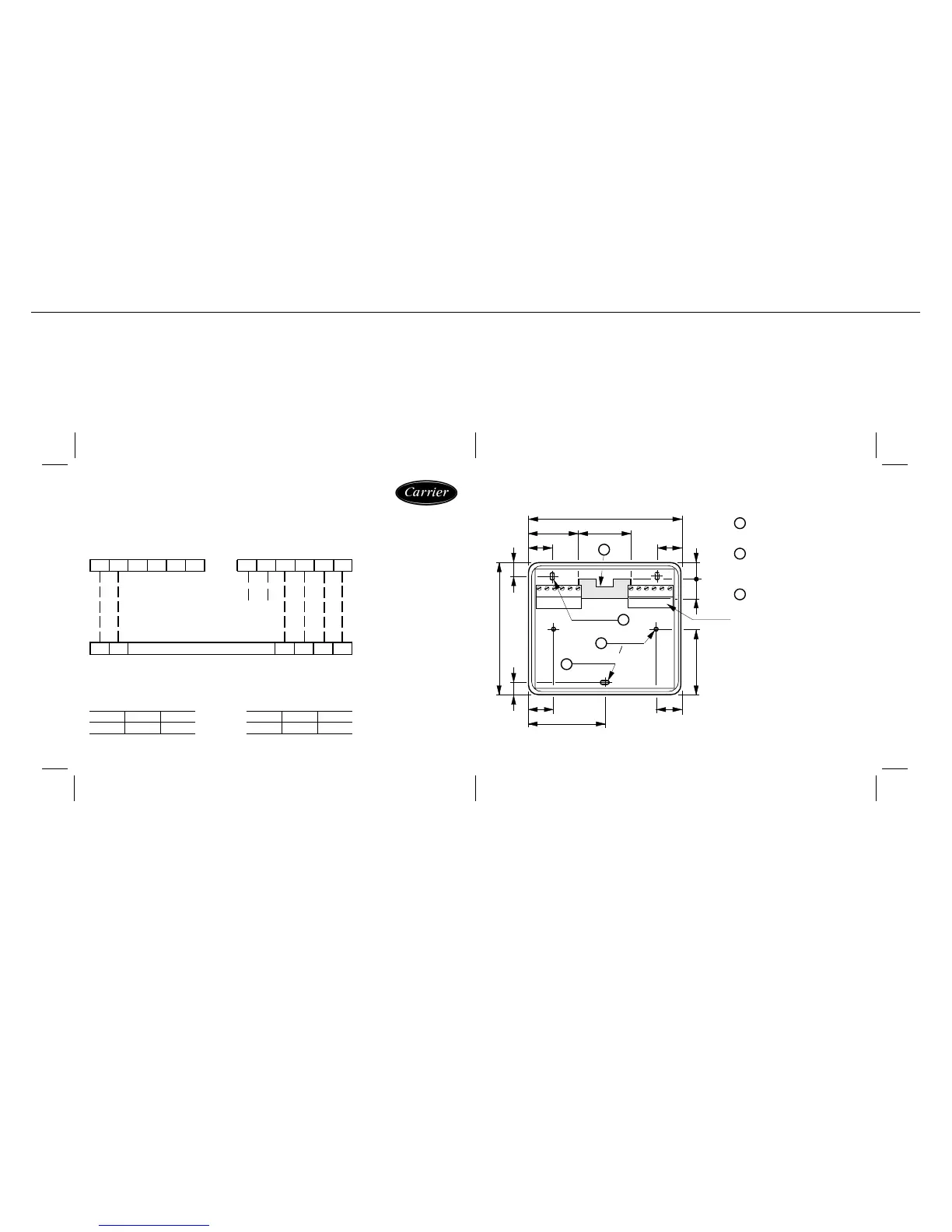
3.- Dimensions ( mm.) Rear Panel
1
2
3
90
30 30
13.5 13.5
14.5 14.5
45
79
6.57.5
812.539
2 Grooves
5.25 x 3.25
2 Holes
o 3.5
Groove
6.25
x 3.25
1
3
2
3
Connection
terminals
Spacing for connection wiring.
Holes for screwing the
Thermostat to a standard
recessed box.
Grooves for screwing the
Thermostat to a wall or flat
surface.