- 28 - - 9 -
10-06-05
Micro No.
Position
MICROS BLOCK S1
1-3-4-5-6
OFF
2
ON
Micro No.
Position
MICROS BLOCK S2
2
OFF
1-3-4-5-6
ON
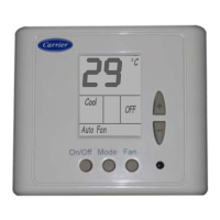
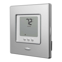
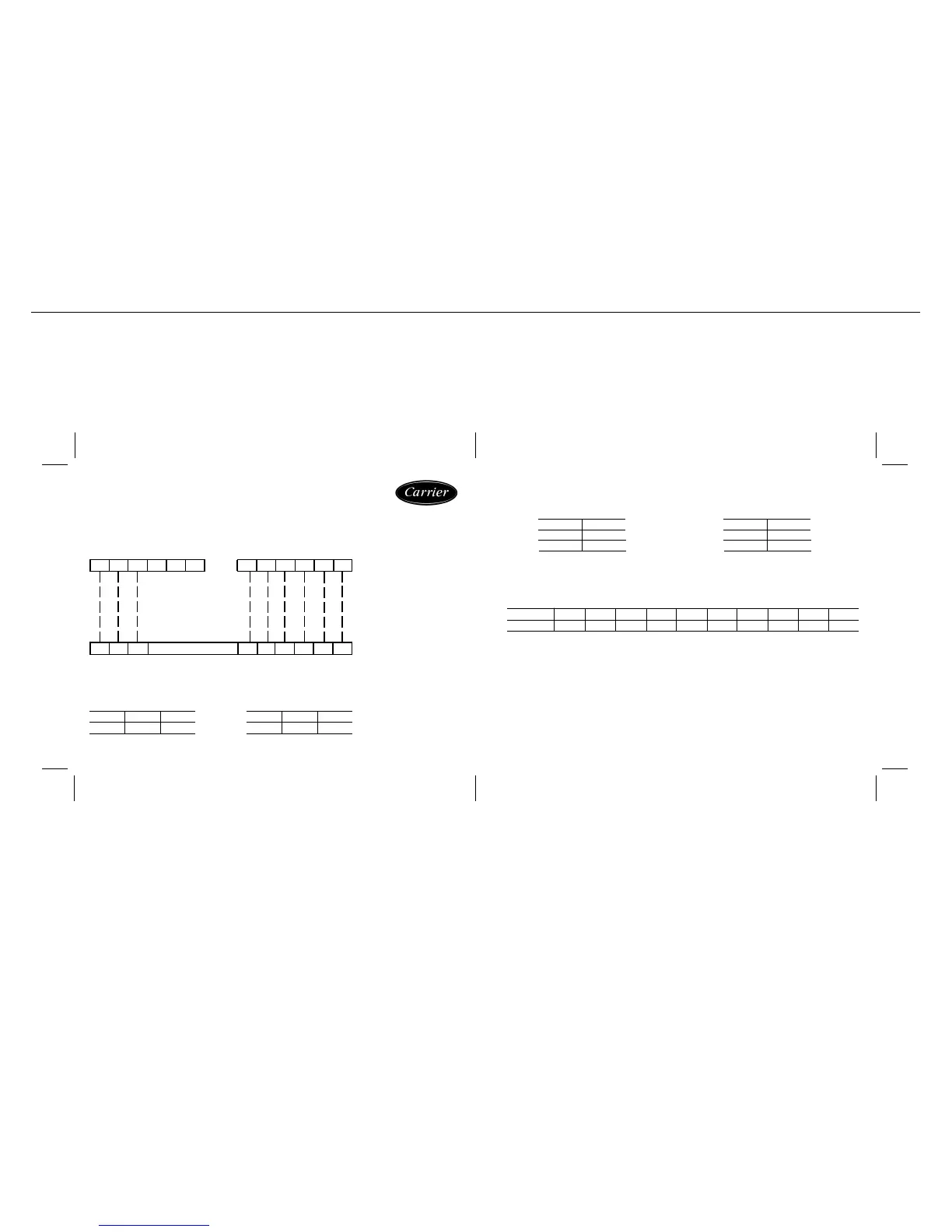
NON-PROGRAMMABLE THERMOSTAT
MODELS « 50PZ / 38PZ + 40PZ 031-075 »
THERMOSTAT TERMINALS
UNIT ELECTRICAL BOX TERMINALS
(Heat pump Models)
REF.- ETN.12
Y 1 G W 1 C R
Y 1 G Y 2 S W 2 ESEW1OCR
OY 2 1 61 7
Temp ºC
Resist. k
5.3 Atmospheric or remote return sensor connection (optional)
NTC Sensor: Temperature~Resistance Features
10.0
100.9
12.8
88.1
15.6
77.1
23.9
52.5
21.1
59.6
18.3
67.7
7.2
115.8
32.2
36.6
29.4
41.2
26.7
46.4
· Disconnect the 24 vac power supply to the thermostat.
· Set micro-switches 1, 2, 3 on block S2 as required.
· Connect the temperature sensor to terminals S and S.
· Reconnect the 24 vac. power supply.
· Use shielded-type wiring to connect the sensor.
Factory configuration includes an internal sensor.
2
1, 3, 4, 5, 6
Micro No.
Position
ON
OFF
BLOCK S1
1, 3, 6
2, 4, 5
Micro No.
Position
ON
OFF
BLOCK S2
The micro-switches are factory configured by default in the following position:
IMPORTANT:
To check if the Unit has a
jumper befween «R & 16»
or «R & 17».
If yes, this jumper must be
removed before doing new
thermostat connections.