EVD4X, ESD4X, WMVC, WMSC: Installation Instructions
Manufacturer reserves the right to change, at any time, specifications and designs without notice and without obligations.
3
Installation of Evaporator Coils
Upflow Coil Installation
The cased coil is designed to fit furnaces of the same width (Fig. 2).
1. Set coil in place on upflow furnace discharge air opening.
2. Ensure coil is level for proper condensate drainage. Do not tip coil
toward condensate drain. Coil casing does not need to be fastened
or screwed to furnace.
3. When installing wider coil on narrower furnace, it is recommended
to use a transition adapter (Fig. 3).
NOTE: On upflow installations where the indoor coil is placed in an
unconditioned space, a 6" wide piece of insulation should be applied and
wrapped around the outside of the coil casing and supply duct contact
point. Consult the furnace installation instructions for any special
requirements when installing the coil to the furnace.
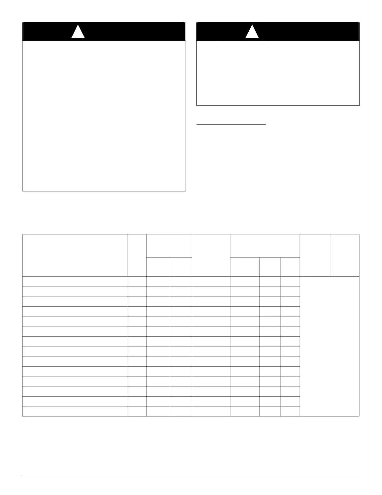
CAUTION
!
IMPORTANT – UNCASED INSTALLATIONS
EVD4X and WMVC units are not intended to be installed uncased
in a plenum and must be installed on an agency listed Furnace.
Failure to comply may damage the coil assembly and can result in
poor performance and property damage.
Any uncased V-Coil installation is not recommended due to factors
such as:
- Mounting dimensions must be held to ensure proper alignment
between the coil and the condensate drain pan.
- Level installation and the relationship of the condensate drain
pan and the coil. If the installation is not level and properly
aligned, condensate blow-off could result.
- Unrestricted airflow across the coil is vital to adequate system
performance.
- The factory-installed foil-faced insulation in the front and rear
of the coil are required to prevent bypass airflow.
- Heat shields for the condensate drain pan (in upflow
installations) and cross members (in downflow installations)
must not be removed.
CAUTION
!
PROPERTY DAMAGE HAZARD
Failure to follow this caution may result in property damage.
Installing coils rotated 90° from the front of the furnace, in upflow or
downflow applications, may cause water blow-off or coil freeze-up due
to the concentration of air on one slab of the coil or lack of air to a slab
of the coil. It is required that on this type of application, a field-supplied
adapter be placed between the coil and furnace to allow air to distribute
properly between all slabs of the coil.
Table 1 – Coil Connections / Orientations
Model
Nom.
Tons
Line Set
Connection Tube
Size, in.
Flush Fit to
Furnace Width,
in. (mm)
Fits Next Smaller Furnace
Width
90°
Rotation to
Furnace
(4" Min.
Transition
Required)
180°
Rotation
to Furnace
Suction Liquid
Equal
Overhang
Offset
Left
Offset
Right
EVM4X24M17A1E / WMVM24417XA1E 2 3/4 3/8 17-1/2 (445) X X X
ALL
Upflow,
Downflow,
Horizontal Right,
Horizontal Left
EVM4X25M17A1E / WMVM25417XA1E 2 3/4 3/8 17-1/2 (445) X X X
EVM4X30M17A1E / WMVM30417XA1E 2.5 3/4 3/8 17-1/2 (445) X X X
EVM4X31M17A1E / WMVM31417XA1E 2.5 3/4 3/8 17-1/2 (445) X X X
EVM4X32M17A1E / WMVC32417XA1E 2.5 3/4 3/8 17-1/2 (445) X X X
EVM4X36M17A1E / WMVM36417XA1E 3 3/4 3/8 17-1/2 (445) X X X
EVM4X42M21A1E / WMVM42421XA1E 3.5 7/8 3/8 21 (533) X X X
EVM4X43M21A1E / WMVM43421XA1E 3.5 7/8 3/8 21 (533) X X X
EVM4X44M21A1E / WMVM44421XA1E 3.5 7/8 3/8 21 (533) X X X
EVM4X48M21A1E / WMVM48421XA1E 4 7/8 3/8 21 (533) X X X
EVM4X49M21A1E / WMVM49421XA1E 4 7/8 3/8 21 (533) X X X
EVM4X60M21A1E / WMVM60421XA1E 5 7/8 3/8 21 (533) X X X
EVM4X60M24A1E / WMVM60424XA1E 5 7/8 3/8 24-1/2 (622) X X X
EVM4X61M24A1E / WMVM61424XA1E 5 7/8 3/8 24-1/2 (622) X X X