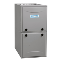
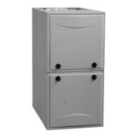
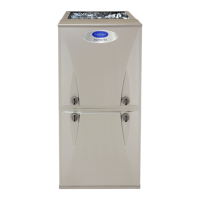
F97CMN and G97CMN: Installation, Start-up, Operating and Service and Maintenance Instructions
Manufacturer reserves the right to change, at any time, specifications and designs without notice and without obligations.
23
See Notes following table.
(SW1-5 and SW4-3 set to OFF, except as indicated. See notes 1 and 2.)
Unit Size: 1002122 Clg/CF Switch settings External Static Pressure (ESP)
Clg Switches SW2-3 SW2-2 SW2-1 0.1 0.2 0.3 0.4 0.5 0.6 0.7 0.8 0.9 1.0
Clg Default: OFF OFF OFF 1820 1825 1840 1845 1840 1835 1825 1805 1780 1770
CF Switches SW3-3 SW3-2 SW3-1
Low-Clg Default: OFF OFF OFF 750 740 745 730 715 See note 4
Cooling Airflow
(SW2)
Low-Cooling
Airflow (SW3)
OFF OFF ON 750 740 745 730 715 See note 4
OFF ON OFF 900 900 915 910 905 See note 4
OFF ON ON 1070 1075 1095 1095 1090 1085 1095 1080 1065 1070
ON OFF OFF 1280 1285 1305 1305 1310 1305 1295 1300 1290 1285
ON OFF ON 1440 1445 1465 1465 1470 1485 1480 1485 1475 1460
ON ON OFF 1820 1825 1840 1845 1840 1835 1825 1805 1780 1770
ON ON ON 2135 2140 2140 2135 2140 2130 2115 2100 2070 2015
Maximum Clg Airflow
2
2160 2165 2175 2170 2160 2150 2135 2120 2065 2020
CF Switches SW3-3 SW3-2 SW3-1
Cont. Fan Default: OFF OFF OFF 750 740 745 730 715 See note 4
Continuous Fan
Airflow (SW3)
OFF OFF ON 750 740 745 730 715 See note 4
OFF ON OFF 900 900 915 910 905 See note 4
OFF ON ON 1070 1075 1095 1095 1090 1085 1095 1080 1065 1070
ON OFF OFF 1280 1285 1305 1305 1310 1305 1295 1300 1290 1285
ON OFF ON 1440 1445 1465 1465 1470 1485 1480 1485 1475 1460
ON ON OFF 1440 1445 1465 1465 1470 1485 1480 1485 1475 1460
ON ON ON 1440 1445 1465 1465 1470 1485 1480 1485 1475 1460
Heating (SW1)
Maximum Heat Airflow
3
1570 1575 1595 1595 1600 1605 1600 1600 1590 1575
Intermediate Heat Airflow
3
950 955 965 975 970 See note 4
Minimum Heat Airflow
3
755 745 750 735 720 See note 4
Unit Size: 1202422 Clg/CF Switch settings External Static Pressure (ESP)
Clg Switches SW2-3 SW2-2 SW2-1 0.1 0.2 0.3 0.4 0.5 0.6 0.7 0.8 0.9 1.0
Clg Default: OFF OFF OFF 1850 1855 1860 1855 1850 1830 1805 1775 1750 1730
CF Switches SW3-3 SW3-2 SW3-1
Low-Clg Default: OFF OFF OFF 930 925 915 900 885 See note 4
Cooling Airflow
(SW2)
Low-Cooling
Airflow (SW3)
OFF OFF ON 765 745 740 705 680 See note 4
OFF ON OFF 930 925 915 900 885 See note 4
OFF ON ON 1095 1100 1110 1105 1085 See note 4
ON OFF OFF 1265 1255 1265 1280 1275 1285 1270 1260 1250 1230
ON OFF ON 1465 1455 1470 1465 1465 1470 1455 1450 1435 1415
ON ON OFF 1850 1855 1860 1855 1850 1830 1805 1775 1750 1730
ON ON ON 2200 2200 2200 2190 2185 2170 2145 2085 1990 1890
Maximum Clg Airflow
2
2200 2200 2200 2190 2185 2170 2145 2085 1990 1890
CF Switches SW3-3 SW3-2 SW3-1
Cont. Fan Default: OFF OFF OFF 930 925 915 900 885 See note 4
Continuous Fan
Airflow (SW3)
OFF OFF ON 765 745 740 705 680 See note 4
OFF ON OFF 930 925 915 900 885 See note 4
OFF ON ON 1095 1100 1110 1105 1085 See note 4
ON OFF OFF 1265 1255 1265 1280 1275 1285 1270 1260 1250 1230
ON OFF ON 1465 1455 1470 1465 1465 1470 1455 1450 1435 1415
ON ON OFF 1465 1455 1470 1465 1465 1470 1455 1450 1435 1415
ON ON ON 1465 1455 1470 1465 1465 1470 1455 1450 1435 1415
Heating (SW1)
Maximum Heat Airflow
3
1815 1820 1825 1820 1815 1795 1775 1745 1720 1700
Intermediate Heat Airflow
3
1095 1100 1110 1105 1085 See note 4
Minimum Heat Airflow
3
905 900 890 875 855 See note 4
Table 7 – Cooling
4
and Heating Air Delivery - CFM (Bottom Return
5
With Filter) (Continued)
 Loading...


