FED “B” Series: Installation Instructions & Homeowner’s Information
Manufacturer reserves the right to change, at any time, specifications and designs without notice and without obligations.
5
A190053B
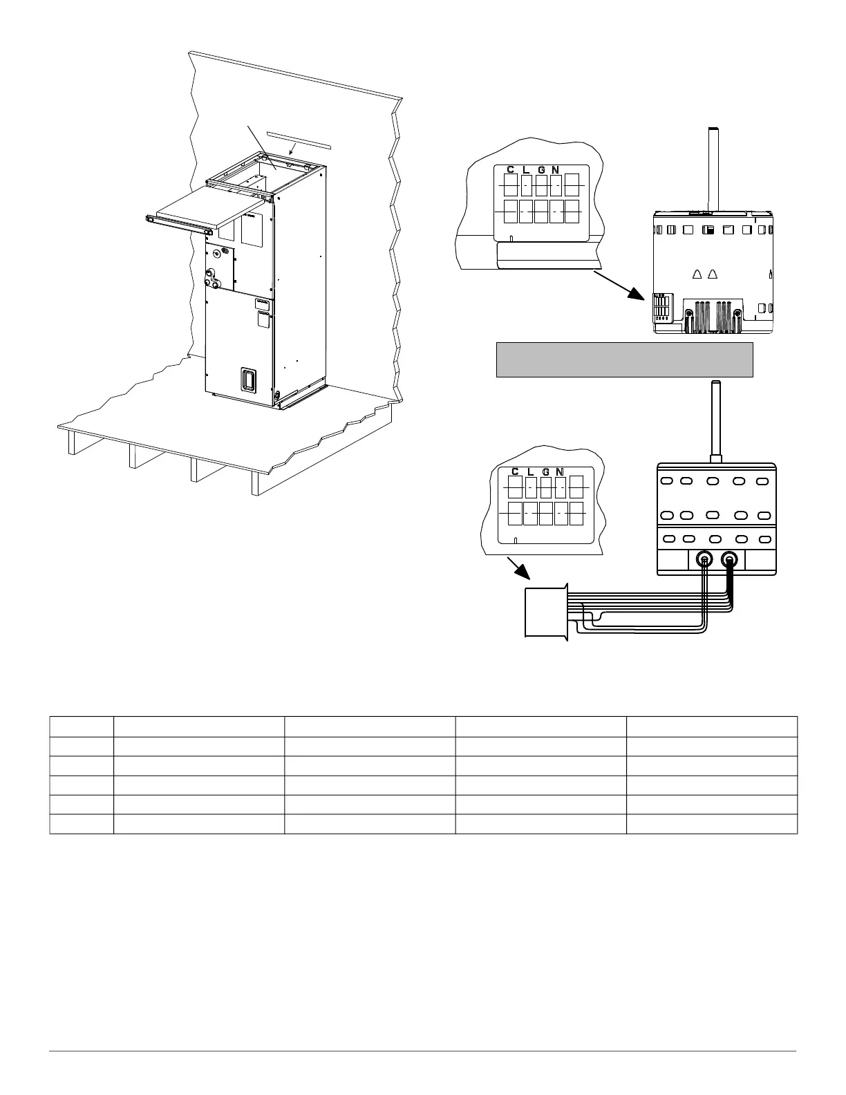
Fig. 10 – Finished Installation with Filter
Filtered Grille Applications
When the unit is located within a closet, a filtered return air grille may be
used as a door or through an adjacent wall into the furnace compartment.
IMPORTANT: When this application is used, the air filter within the unit
must be removed.
Minimum CFM and Motor Speed Selection
(applicable to on-site HVAC contractor)
Units with electric heaters require a minimum CFM. Refer to the unit
wiring label to ensure that the fan speed selected is not lower than the
minimum fan speed indicated.
Fan speed selection is done at the fan motor. To change motor speeds,
reposition wire at fan motor speed terminals labeled 1-2-3. See Fig. 11.
Units with or without electric heaters require a minimum CFM. Refer to
the unit wiring label to ensure that the fan speed selected is not lower
than the minimum fan speed indicated.
A11048
Fig. 11 – Motor Speed Selection
‡ High Static Speed Tap. The motor may or may not have a yellow wire plugged into this tap. If present, the yellow thermostat input is used for high static cooling / heat pump application if
necessary.
To change motor speeds disconnect the WHITE fan lead from motor
connector terminal #2 (factory default position) and move to the desired
speed tap.
Speed taps 1, 2, and 3 have a 90 second blower off time delay
pre-programmed into the motor. Speed tap 2 (WHITE wire) is used for
electric heat only. Speed tap 5 is NOT used for electric heating. Also, see
Fig. 11 for motor speed selection location.
Sequence of operations
Continuous Fan (Whole House Ventilation)
Thermostat closes R to G. G sends signal direct to motor which
completes circuit to indoor blower motor. When G is de-energized, there
is a 90 second off delay before indoor blower motor stops.
Electric Heat or Emergency Heat Mode
Thermostat closes R to W. W energizes electric heat relay(s) which
completes circuit to heater element(s). W also energizes the indoor
blower motor. When W is de-energized, electric heat relay(s) opens and
the indoor blower motor is de-energized and stops.
OPTIONAL SCREW
SPACER
(IF NECESSARY)
1 2 3 4 5
Speed Taps may be located on motor,
or on plug close to motor.
CLGN
1 2 3 4 5
Table 2 – Speed Tap Selection at Motor Connector
FE(D,U)24*‡ FE(D,U)36*‡ FE(D,U)48*‡ FE(D,U)60*‡
Tap 1 Continuous Fan Continuous Fan Continuous Fan Continuous Fan
Tap 2 Electric Heat Electric Heat Electric Heat Electric Heat
Tap 3 Not used for electric heat Not used for electric heat Not used for electric heat Not used for electric heat
Tap 4 Not used for electric heat Not used for electric heat Not used for electric heat Not used for electric heat
Tap 5¨ Not used for electric heat Not used for electric heat Not used for electric heat Not used for electric heat
 Loading...


