FED “B” Series: Installation Instructions & Homeowner’s Information
Manufacturer reserves the right to change, at any time, specifications and designs without notice and without obligations.
2
door.
POSITION UNIT
Allow space for wiring, piping, and servicing unit.
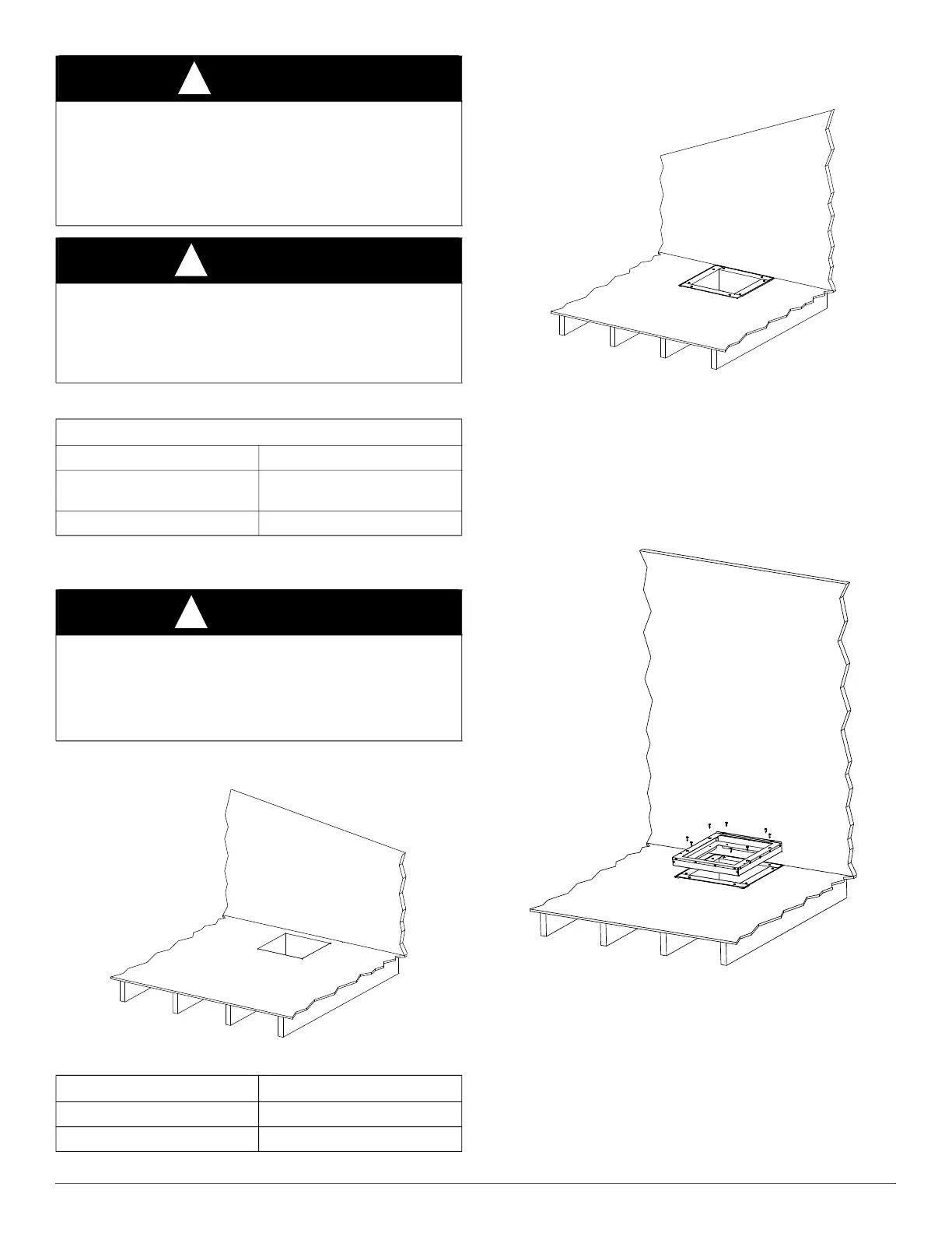
1. Cut a hole in the floor where the unit will be located. See Fig. 1 and
the floor cutout dimensions table.
A190097
2. Apply a bead of UL 181 rated caulk or approved duct mastic around
the perimeter of the hole, and install the plenum and make
appropriate connections to the ductwork. See Fig. 2.
A180300
Fig. 2 – Add Plenum and Ductwork
3. Apply a bead of UL 181 rated caulk or approved duct mastic around
the perimeter of the plenum, and then install the floor base supplied
with the unit over the plenum. Attach with four 1² length (min)
wood screws through the plenum and into the floor. See Fig. 3.
4. Place the optional accessory Floor Base supplied with the unit over
the plenum and attach with 1² length (min) screws, through plenum
and into floor. See Fig 3.
NOTE: Optional floor base not required for non-combustible flooring.
A180301
Fig. 3 – Floor Base
NOTE: The unit is shipped with the supply air side UP. Do steps 5 and
6 before inverting before installing.
5. Remove electrical knockouts from desired wire entry locations for
high voltage and thermostat wire.
6. Remove the filter and its access door before inverting the unit.
7. Invert the unit and place it onto the base. The unit flanges will fit
into the base opening.
8. Slide the unit to the back of the base. Make sure the tabs go into the
slots of the casing when you slide the unit back. See Fig. 4.
CAUTION
!
PROPERTY DAMAGE HAZARD
Failure to follow this caution may result in poor unit performance
and/or product damage.
Never operate the unit without a filter. For those applications where
access to an internal filter is impractical, a field-supplied filter must be
installed in the return air stream.
WARNING
!
FIRE HAZARD
Failure to follow this warning could result in personal injury or death,
or property damage.
When heaters are installed, maintain clearances from combustible
materials as specified on the unit rating plate.
Table 1 – Required Clearances
ALL MODELS - Space, inches
Back and Sides 0”
Front
In Closet - 6” to closet door
In Alcove - 24” for access
Ducts 0”
WARNING
!
STRUCTURAL DAMAGE
Failure to follow this warning could result in personal injury or death,
or property damage.
The supplied noncombustible floor base is required for downflow
applications with electric heat strips.
Fig. 1 – Floor Cutout Dimensions
Furnace Model Number Hole Size
FED002410* thru FED004815* 14.5” x 14.5”
FED006020* 17.5” x 17.5”
 Loading...


