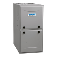
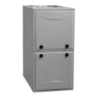
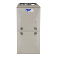
FED “B” Series: Installation Instructions & Homeowner’s Information
Manufacturer reserves the right to change, at any time, specifications and designs without notice and without obligations.
4
Thermostat Wiring Connections
For complete electric furnace electrical specs, see Table 5.
For Fig. 7:
• R = 24V
• G = Continuous Fan
• W2, W3, E = Electric Heat
• C = Common
A190052B
Fig. 7 – Wiring Layout - Furnace
Transformer Information
(applicable to on-site HVAC contractor)
For wiring of add-on cooling or heat pump system, see instructions
included with add-on equipment.
The transformer in the furnace is factory wired for 230V operation. For
208V applications, the installing contractor should disconnect the black
wire from the 230V terminal on transformer and connect it to the 208V
terminal. See Fig. 8.
A05182
Fig. 8 – Transformer Connections
Ground Connections
NOTE: Grounding may be accomplished by using grounding lugs
provided in the control box.
1. Remove the door. See Fig. 9.
NOTE: Do not over-tighten the screws in the next step. Over-torquing
will deform the cabinet.
2. Install two 3-inch flanged head screws or screws with washers in
the lower front cavity of the furnace base and into the floor.
3. If desired, place an optional screw from inside the upper back panel
into a stud or backer to add stability. Use a self-tapping screw or
drill a pilot hole through the casing and into a stud. See Fig. 10.
4. If necessary, add a spacer between the wall and back of the unit to
keep the unit level.
5. Replace the filter and its access door.
6. Connect wire protection plate to downflow base after wiring is
complete, and before using long screws to attach front base of
cabinet to floor as shown in Fig. 9.
A190083C
Fig. 9 – Unit Attachment
(shows B series circuit breaker configuration)
R
G
W
Y
THERMOSTAT
R
G
W
2
W
3
E
C
FURNACE
(CONTROL)
RED
WHT
WHT
BLU
VIO
C
BRO
HI or Y2
YEL
BLU or GRY
230
C
208
BRN
RED
YEL
BLK
SECONDARY
PRIMARY
WARNING
!
ELECTRICAL SHOCK HAZARD
Failure to establish uninterrupted or unbroken ground could result in
personal injury or death.
According to NEC, ANSI/NFPA 70, and local codes, the cabinet must
have an uninterrupted or unbroken ground in order to minimize
potential for personal injury or death if an electrical fault should occur.
The ground may consist of electrical wire or metal conduit when
installed in accordance with existing electrical codes. If conduit
connection uses reducing washers, a separate ground wire must be
used.
WIRING PROTECTION
PLATE (INSTALL BEFORE
BASE SCREWS)
BASE SCREWS
INSTALLED
IN STEP 2
ON
OFF

 Loading...


