FMA5L, FMA5X: Installation Instructions
Manufacturer reserves the right to change, at any time, specifications and designs without notice and without obligations.
6
Mount Fan Coil
Fan Coil Mounting Options
The fan coil comes standard with two different options for mounting:
wall mount or frame mount. Both mounting options require the unit to be
level from side to side and from front to back in order to allow
condensate to properly drain from the unit. Failure to do this will result
in condensate leaking out from the unit, potentially causing structural
damage to the surrounding support structures, drywall, carpet, etc.
around the unit. Also, both mounting structures require the ability to
accommodate a minimum of load of 150 pounds. Failure to do this will
cause damage to the support structure and potentially damage the unit.
A13011
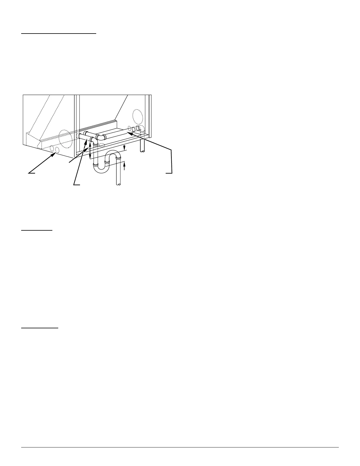
Fig. 2 – Condensate Drain
Wall Mount
The fan coil comes standard with a wall mounting bracket and fan coil
mounting bracket. Refer to Fig. 4 for more detail.
1. Remove the wall mounting bracket from the back of the unit by
removing one screw which attaches the bracket to the fan coil.
NOTE: Discard the screw after you have removed the wall mounting
bracket.
2. Install bracket on the wall by using three wood screws (not
provided) per wall-mount bracket. Make sure the bracket is level in
order to provide proper drainage from the unit.
NOTE: Do not attach the wall mounting bracket into unsupported
drywall. Make sure that the wood screws are going into a structure that
can support a minimum load of 150 pounds.
3. Lift the fan coil above the wall mounting bracket and attach the unit
to the installed bracket. Refer to Fig. 4.
Frame Mount
The fan coil comes with eight clearance holes, four on each side. These
holes are used to mount the fan coil inside a frame structure (Fig. 5).
When mounting in this fashion, make sure that the wood screws are
mounted from within the fan coil and not outside of the unit. Installing
the screws from outside of the unit may damage the coil.
After moving unit into place, install refrigerant tubing as follows:
1. Route tubing to connection points, taking care not to block service
access.
2. Remove plugs from liquid and vapor lines.
3. Braze connections using either silver bearing or non-silver bearing
brazing material. Do not use soft solder (materials which melt
below 800°F / 427°C). Consult local code requirements. Always
flow nitrogen through the system refrigerant lines while brazing.
4. Pressurize system and leak-test. Repeat procedure until leak-free.
PRIMARY
DRAIN
2" / 51mm
MIN DRAIN
ALTERNATE
DRAIN EXITS ON
SECONDARY
DRAIN
(TRAP EXTERNAL
TO UNIT)
NOTE: Use plastic pipe from
condensate pan to
exterior of fan coil.
2" / 51mm
MIN
EITHER SIDE OF UNIT
 Loading...