11
PERFORMANCE DATA (cont)
CFM --- C u b i c F t p e r M in u t e EWB --- Entering Wet Bulb _F(_C) LWB --- L e a v i n g We t B u l b _F(_C) TC --- Gross Cooling Capacity 1000 Btuh
SHC --- Gross Sensible Capacity 1000
Btuh
BF --- By p a ss Fa c t o r MBH --- 1000 Btuh
NOTES:
1. Contact manufacturer for cooling capacities at conditions
other than shown in table.
2. Formulas:
Leaving db = entering db --sensible heat cap.
1.09 x CFM
Leaving wb = wb corresponding to enthalpy of air leaving
coil (h
lwb
)
h
lwb
=h
ewb
--total capacity (Btuh)
4.5xCFM
where h
ewb
= enthalpy of air entering coil. Direct interpola-
tion is permissible. Do not extrapolate.
3. SHC is based on 80_F(27_C) db temperature of air enter-
ing coil. Below 80_F(27_C) db, subtract (Correction Fact-
or x CFM) from SHC. Above 80_F(27_C) db, add (Cor-
rectionFactorxCFM)toSHC.
4. Bypass Factor = 0 indicates no psychometric solution. Use
bypass factor of next lower EWB for approximation.
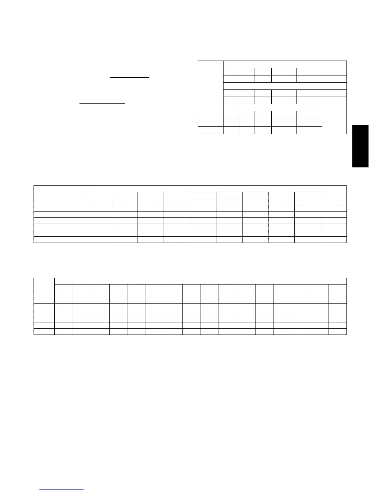
SHC CORRECTION FACTOR
BYPASS
FACTOR
ENTERING AIR DRY--BULB TEMPERATURE (_F)
79 78 77 76 75 Under 75
81 82 83 84 85 Over 85
ENTERING AIR DRY--BULB TEMPERATURE (_C)
26 25 25 24 24 Under 75
27 28 28 29 29 Over 85
Correction Factor
0.10 .098 1.96 2.94 3.92 4.91
Use
formula
shown
below
0.20 0.87 1.74 2.62 3.49 4.36
0.30 0.76 1.53 2.29 3.05 3.82
Interpolation is permissible.
Correction Factor = 1.09 x (1 --- BF) x (db --- 80)
MINIMUM CFM AND MOTOR SPEED SELECTION
FAN COIL SIZES
FX
HEATER kW
3 5 8 9 10 15 18 20 24 30
019 525 525 525 — 600* — — — — —
025 700 700 700 — 700 775* — — — —
031 — 875 875 — 875 875 — 1060* — —
037 — 1050 970 970 970 920 — 1040 — —
043 — — 1225 1225 1225 1225 1225 1225 — —
049 — — 1400 1400 1400 1400 1400 1400 1400 1400
061 — — 1750 1750 1750 1750 1750 1750 1750 1750
* Indicates medium speed (blue). All other motor speeds at low tap.
AIR DELIVERY PERFORMANCE CORRECTION COMPONENT PRESSURE DROP (in wc)
AT INDICATED AIRFLOW (DRY--TO--WET COIL)
FX
SIZE
CFM
500 600 700 800 900 1000 1100 1200 1300 1400 1500 1600 1700 1800 1900 2000
019 0.034 0.049 0.063 --- --- --- --- --- --- --- --- --- --- --- --- --- --- --- --- --- --- --- --- --- --- --- --- --- ---
025 0.016 0.027 0.038 0.049 0.059 --- --- --- --- --- --- --- --- --- --- --- --- --- --- --- --- --- --- --- --- --- ---
031 --- --- --- --- --- --- 0.049 0.059 0.070 0.080 --- --- --- --- --- --- --- --- --- --- --- --- --- --- --- --- --- ---
037 --- --- --- --- --- --- --- --- --- --- 0.055 0.064 0.073 0.081 --- --- --- --- --- --- --- --- --- --- --- --- --- ---
043 --- --- --- --- --- --- --- --- --- --- --- --- --- --- 0.049 0.056 0.063 0.070 --- --- --- --- --- --- --- --- --- ---
049 --- --- --- --- --- --- --- --- --- --- --- --- --- --- --- --- --- --- 0.038 0.043 0.049 0.054 0.059 --- --- --- ---
061 --- --- --- --- --- --- --- --- --- --- --- --- --- --- --- --- --- --- --- --- --- --- 0.027 0.031 0.035 0.039 0.043
FX4D

 Loading...