FEM4X, FEM4P, REM4X, REM4P, FXM4X: Installation Instructions
Manufacturer reserves the right to change, at any time, specifications and designs without notice and without obligations.
10
A95294
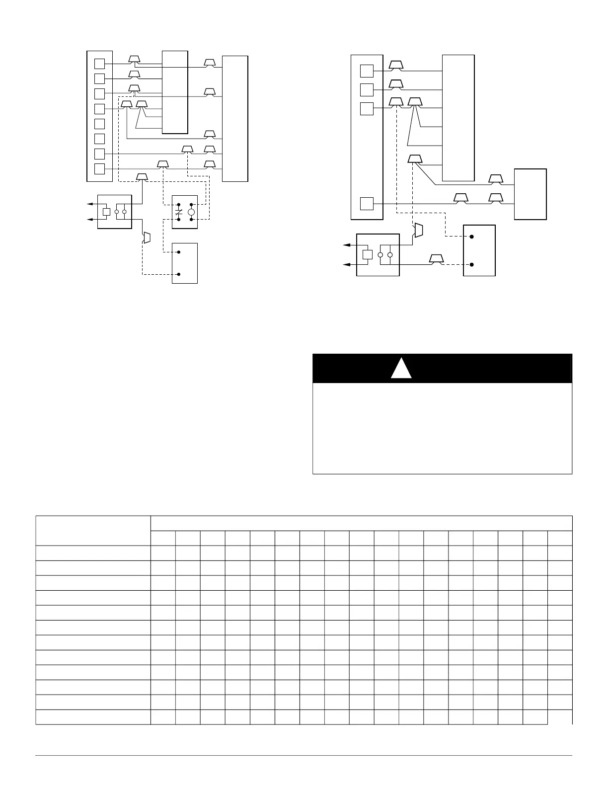
Fig. 19 – Wiring Layout of Humidifier to Heat Pump
Start-up procedure
Refer to outdoor unit Installation Instructions for system start-up
instructions and refrigerant charging method details.
CARE AND MAINTENANCE
The system should be regularly inspected by a qualified service
technician. Consult the servicing dealer for recommended frequency.
Between visits, the only consumer service recommended or required is
air filter maintenance and condensate drain operation.
AIR FILTER
Inspect air filters at least monthly and replace or clean as required.
Disposable type filters should be replaced. Reusable type filters may be
cleaned by soaking in mild detergent and rinsing with cold water. Install
filters with the arrows on the side pointing in the direction of air flow.
A95295
Fig. 20 – Wiring Layout of Humidifier to Fan Coil
with Electric Heat
CONDENSATE DRAIN
During the cooling season check at least monthly for free flow of
drainage and clean if necessary.
R
G
C
E
L
O
Y
THERMOSTAT
R
R
C
O
Y
G
C
W
2
W
2
W
2
W
3
E
FAN COIL
(CONTROL)
HEAT PUMP
(CONTROL)
RED
GRY
BRN
WHT
WHT
BLU
VIO
HUMIDISTAT
RELAY
FAN HUMIDIFIER
115V
M
CAUTION
!
PRODUCT DAMAGE HAZARD
Failure to follow this caution may result in poor unit performance
and/or product damage.
Never operate unit without a filter. Factory authorized filter kits may be
used when locating the filter inside the unit. For those applications
where access to an internal filter is impractical, a field-supplied filter
must be installed in the return air duct system.
R
G
W
Y
THERMOSTAT
R
G
W
2
W
3
E
C
FAN COIL
(CONTROL)
C
Y
AIR COND.
HUMIDISTAT
FAN HUMIDIFIER
115V
RED
GRY
WHT
WHT
BLU
VIO
BRN
M
Table 4 – Air Delivery Performance Correction Component Pressure Drop (in. w.c.)
at Indicated Airflow (Dry to Wet Coil)
UNIT SIZE
CFM
500 600 700 800 900 1000 1100 1200 1300 1400 1500 1600 1700 1800 1900 2000
18
0.034 0.049 0.063 — — — — — — — — — — — — —
FEM4P24
— 0.049 0.063 0.076 0.089 — — — — — — — — — — —
FEM4X24 & REM4X24
— 0.026 0.038 0.049 0.059 — — — — — — — — — — —
FXM4X24
0.016 0.027 0.038 0.049 0.059 — — — — — — — — — — —
30
— — — 0.049 0.059 0.070 0.080 — — — — — — — — —
36
— — — — — 0.070 0.080 0.090 0.099 — — — — — — —
FXM4X36
— — — — — 0.055 0.064 0.073 0.081 — — — — — — —
42
— — — — — — — 0.049 0.056 0.063 0.070 — — — — —
48
— — — — — — — — — 0.063 0.070 0.076 0.083 0.090 — —
FXM4X48
— — — — — — — — — 0.038 0.043 0.049 0.054 0.059 — —
60
— — — — — — — — — — — 0.049 0.054 0.059 0.065 0.070
FXM4X60
— — — — — — — — — — — 0.027 0.031 0.035 0.039 0.043
 Loading...