FEM4X, FEM4P, REM4X, REM4P, FXM4X: Installation Instructions
Manufacturer reserves the right to change, at any time, specifications and designs without notice and without obligations.
9
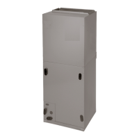
traps (Fig. 16). Factory approved condensate traps are available
(accessory part number EBAC01CTK).
To connect drainlines, the drain connection knock-outs must be
removed. Use a knife to start the opening near the tab and using pliers,
pull the tab to remove the knock-out. Clean the edge of the opening if
necessary. After drain fittings are installed, caulk the seam between the
fitting and the cover to retain the low leak rating of the unit.
A03002
Fig. 16 – Recommended Condensate Trap
A03013
Fig. 17 – Insufficient Condensate Trap
It is recommended the PVC fittings be used on the plastic condensate
pan. Do not over-tighten. Finger-tighten plus 1-1/2 turns. Use pipe dope
to ensure proper seal.
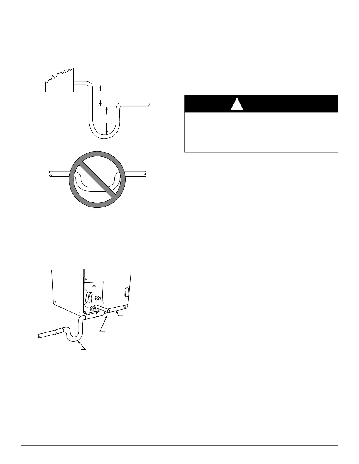
Install traps in the condensate lines as close to the coil as possible (refer
to Fig. 18), but avoid blocking filter access panel.
A03003
Fig. 18 – Condensate Drain
Install drain lines below the bottom of the drain pan and pitch the drain
lines down from the coil at least 1/4 inch per foot of run (6mm per 0.3m).
Horizontal runs over 15 feet (5m) long must also have an anti-siphon air
vents (stand pipes), installed ahead of the horizontal runs. Extremely
long horizontal runs may require oversized drain lines to eliminate air
trapping.
Route primary drain line to the outside or to a floor drain. Check local
codes before connecting to a waste (sewer) line.
Route the secondary drain line to a place in compliance with local
installation codes where it will be noticed when unit is operational.
Condensate flowing from secondary (overflow) drain indicates a
plugged primary drain - unit requires service or water damage will occur.
Prime all traps, test for leaks, and insulate in areas where sweating of
the traps and drain lines could potentially cause water damage. Consult
local codes for additional requirements or precautions.
If a gravity drain cannot be used, install a condensate pump. Install the
pump as close to the indoor section as possible.
ACCESSORIES
HUMIDIFIER
Connect humidifier and humidistat to fan coil unit as shown in Fig. 20
and Fig. 19.
SEQUENCE OF OPERATION
CONTINUOUS FAN
Thermostat closes R to G. G sends signal direct to motor which
completes circuit to indoor blower motor. When G is de-energized, there
is a 90 second off delay before indoor blower motor stops.
COOLING MODE
Thermostat energizes R to G, R to Y, and R to O (heat pump only). G
sends signal direct to motor, which completes circuit to indoor blower
motor. When G is de-energized, there is a 90-second off delay before
indoor blower motor stops.
HEAT PUMP HEATING MODE
Thermostat energizes R to G and R to Y. G sends signal direct to motor,
which completes circuit to indoor blower motor. When G is
de-energized, there is a 90-second off delay before indoor blower motor
stops.
HEAT PUMP HEATING WITH AUXILIARY
ELECTRIC HEAT
Thermostat energizes R to G, R to Y, and R to W. G energizes indoor
blower motor. W energizes electric heat relay(s) which completes circuit
to heater element(s). When W is de-energized, electric heat relay(s)
open, turning off heater elements. When G is de-energized, the indoor
blower motor is de-energized and stops.
ELECTRIC HEAT OR EMERGENCY HEAT MODE
Thermostat closes R to W. W energizes electric heat relay(s) which
completes circuit to heater element(s). W also energizes the indoor
blower motor. When W is de-energized, electric heat relay(s) opens and
the indoor blower motor is de-energized and stops.
2” MIN
(51 mm)
UNIT
2” MIN
(51 mm)
DO NOT USE SHALLOW RUNNING TRAPS!
FILTER
ACCESS
PANEL
SECONDARY DRAIN WITH
APPROPRIATE TRAP REQUIRED
(USE FACTORY KIT OR
FIELD-SUPPLIED TRAP)
PRIMARY TRAP REQUIRED
(USE FACTORY KIT OR
FIELD-SUPPLIED TRAP OF
SUFFICIENT DEPTH.
STANDARD P-TRAPS ARE
NOT SUFFICIENT. SEE
FIGURE OF RECOMMENDED
CONDENSATE TRAP)
CAUTION
!
PRODUCT DAMAGE HAZARD
Failure to follow this caution may result in product or property damage.
Use only full size P-traps in the condensate line (Fig. 16). Shallow
running traps are inadequate and DO NOT allow proper condensate
drainage (Fig. 17).
 Loading...