FEM4X, FEM4P, REM4X, REM4P, FXM4X: Installation Instructions
Manufacturer reserves the right to change, at any time, specifications and designs without notice and without obligations.
6
AIR DUCTS
Connect supply-air duct over the outside of 3/4" flanges provided on
supply-air opening. Secure duct to flange using proper fasteners for type
of duct used, and seal duct-to-unit joint.
It is a recommendation, but not a requirement, to use flexible
connections between ductwork and unit to prevent transmission of
vibration. When electric heater is installed, use heat-resistant material
for flexible connector between duct work and unit at discharge
connection. Duct work passing through unconditioned space must be
insulated and covered with vapor barrier.
DUCT WORK ACOUSTICAL TREATMENT
Metal duct systems that do not have a 90 degree elbow and 10 feet of
main duct before first branch takeoff may require internal acoustical
insulation lining. As an alternative, fibrous duct work may be used if
constructed and installed in accordance with the latest edition of
SMACNA construction standard on fibrous glass ducts. Both acoustical
lining and fibrous duct work shall comply with National Fire Protection
Association as tested by UL Standard 181 for Class 1 air ducts.
ELECTRICAL CONNECTIONS
These Fan Coils do not have a printed circuit board (PCB), they have a
low voltage circuit protective fuse (3 amp) inline on the wire harness.
Speed selections are made at the fan motor with the Blue wire. The
motor is pre-programmed with the time-delay circuit on some of the
speed taps.
Before proceeding with electrical connections, make certain that supply
voltage, frequency, phase, and circuit ampacity are as specified on the
unit rating plate. See unit wiring label for proper field high and low
voltage wiring.
Make all electrical connections in accordance with the NEC and any
local codes or ordinances that may apply. Use copper wire only. The unit
must have a separate branch electric circuit with a field-supplied
disconnect switch located within sight of and readily accessible from the
unit.
NOTE: When a pull-out type disconnect is removed from the unit, only
the Load side of the circuit is de-energized. The Line side remains live
until the main (remote) disconnect is turned off.
LINE VOLTAGE CONNECTIONS
Fan Coils installed without electric heat require the use of a
factory-authorized Power Plug Kit (accessory part number
EBAC01PLG). This kit provides the electrical connections necessary to
supply the unit with 208/230V power when electric heat is not present.
For units without electric heat:
1. Connect 208/230V power leads from field disconnect to yellow and
black stripped leads on Power Plug (accessory part number
EBAC01PLG).
2. Connect ground wire to unit ground lug.
3. When installing an electric heater, remove and discard power plug
(if equipped) from fan coil and connect male plug from heater to
female plug from unit wiring harness. (See Electric Heater
Installation Instructions.)
24V CONTROL SYSTEM
Connection to Unit
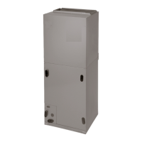
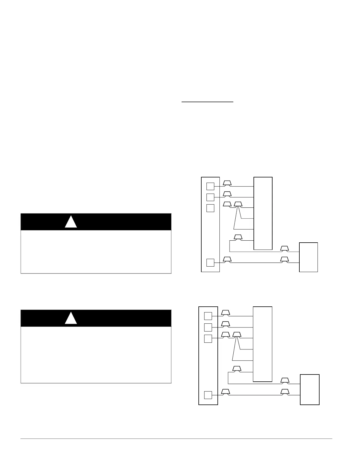
Wire low-voltage in accordance with wiring label on the blower (also
refer to Fig. 9 through Fig. 12). Use 18 AWG color-coded, insulated
(35°C minimum) wire to make the low-voltage connections between the
thermostat, the unit, and the outdoor equipment. If the thermostat is
located more than 100 feet from the unit (as measured along the low
voltage wire), use 16 AWG color-coded, insulated (35°C minimum)
wire. All wiring must be NEC Class 1 and must be separated from
incoming power leads. Refer to outdoor unit wiring instructions for
additional wiring recommendations.
.
A94058
Fig. 9 – Wiring Layout -Air Conditioning Unit
(Cooling Only)
A94059
Fig. 10 – Wiring Layout -Air Conditioning Unit
(Cooling and 1-Stage Heat)
WARNING
!
ELECTRICAL SHOCK OR UNIT DAMAGE HAZARD
Failure to follow this warning could result in personal injury, death,
and/or unit damage.
If a disconnect switch is to be mounted on unit, select a location where
drill and fasteners will not contact electrical or refrigeration
components.
WARNING
!
ELECTRICAL SHOCK OR UNIT DAMAGE HAZARD
Failure to follow this warning could result in personal injury or death.
Turn off the main (remote) disconnect device before working on
incoming (field) wiring.
Incoming (field) wires on the line side of the disconnect found in the
fan coil unit remain live, even when the pull-out is removed. Service
and maintenance to incoming (field) wiring cannot be performed until
the main disconnect switch (remote to the unit) is turned off.
R
G
W
Y
THERMOSTAT
RED
GRY
WHT
BLU
VIO
BRN
WHT
R
G
W
2
W
3
E
C
FAN COIL
(CONTROL)
C
Y
AIR COND.
R
G
W
Y
THERMOSTAT
R
G
W
2
W
3
E
C
FAN COIL
(CONTROL)
C
Y
AIR COND.
RED
GRY
WHT
WHT
BLU
VIO
BRN
 Loading...