FEM4X, FEM4P, REM4X, REM4P, FXM4X: Installation Instructions
Manufacturer reserves the right to change, at any time, specifications and designs without notice and without obligations.
5
A00071A
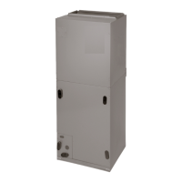
Fig. 6 – Conversion for Horizontal Right Applications - A-Coil
A07141
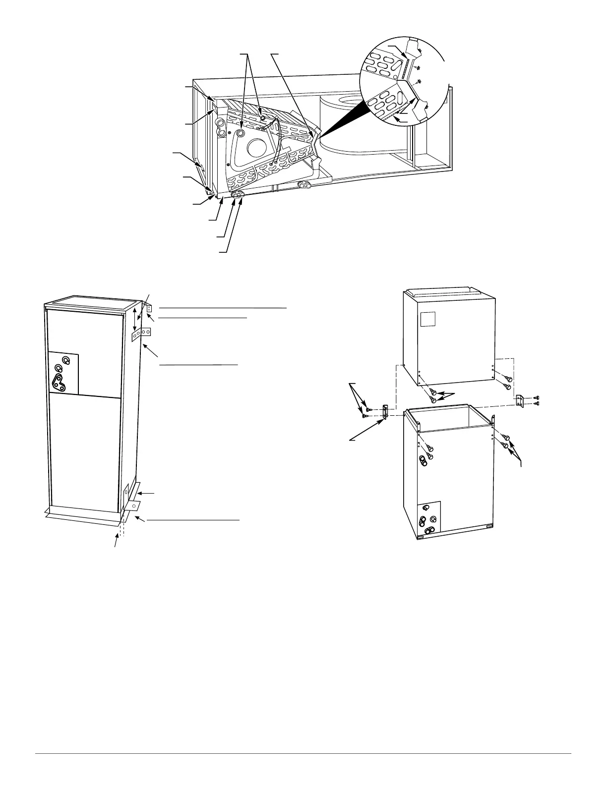
Fig. 7 – Mobile Home or Manufactured Housing Applications
10. Remove 2 oval coil access panel plugs and reinstall into holes on
left side of coil access panel and fitting panel.
11. Remove insulation knockouts on right side of coil access panel.
12. Reinstall access fitting panels, aligning holes with tubing
connections and condensate pan connections. Be sure to reinstall
metal clip between fitting panel and vertical condensate pan.
13. After brazing, make sure liquid and suction tube grommets are in
place to prevent air leaks and cabinet sweating.
MANUFACTURED HOUSING AND MOBILE HOME
APPLICATIONS
1. Fan coil unit must be secured to the structure using field-supplied
hardware.
A95293
Fig. 8 – Removal of Brackets on Modular Units
2. Allow a minimum of 24 inches (610mm) clearance from access
panels.
3. Recommended method of securing for typical applications:
a. If fan coil is away from wall, attach pipe strap to top of fan coil
using No. 10 self-tapping screws. Angle strap down and away
from back of fan coil, remove all slack, and fasten to wall stud of
structure using 5/16" lag screws. Typical both sides of fan coil.
b. If fan coil is against wall, secure fan coil to wall stud using 1/8"
wide right-angle brackets. Attach brackets to fan coil using No.
10 self tapping screws and to wall stud using 5/16" lag screws
(Fig. 7).
NOTE: Modular units can be disassembled and components moved
separately to installation area for reassembly. This process
accommodates small scuttle holes and limiting entrances to installation
sites (Fig. 8).
COIL
SUPPORT
RAIL
COIL
BRACKET
DRAIN PAN
SUPPORT
BRACKET
COIL
SUPPORT
RAIL
COIL
BRACKET
HORIZONTAL
DRAIN PAN
PRIMARY DRAIN
HORIZONTAL RIGHT
SECONDARY DRAIN
HORIZONTAL RIGHT
REFRIGERANT
CONNECTIONS
AIR SEAL
ASSEMBLY
A
B
C
HORIZONTAL
RIGHT
APPLICATION
DOWN FLOW
BASE KIT (KFACB)
UNIT AGAINST WALL
1/8" (3.18 mm) THICK ANGLE
MOUNTING BRACKET
(TYPICAL BOTH SIDES)
SECURE FAN COIL TO STRUCTURE
UNIT AWAY FROM WALL
PIPE STRAP
(TYPICAL BOTH SIDES)
OR
SECURE UNIT TO FLOOR
ANGLE BRACKET OR PIPE STRAP
4” (101.6 mm) MAX
4” (101.6 mm) MAX
2 SCREWS
2 SCREWS
REAR CORNER
BRACKET
BLOWER BOX
COIL BOX
2 SCREWS