iv
T--295
LIST OF ILLUSTRATIONS
FIGURE NUMBER Page
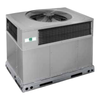
Figure 1-1. A/C Component Identification 1-1..................................................
Figure 1-2. Apex Unit Components 1-2........................................................
Figure 1-3. Condensing Section Components 1-3................................................
Figure 1-4. Evaporator Section Components 1-4.................................................
Figure 1-5. Air Flow Paths 1-6..............................................................
Figure 1-6. Refrigerant Flow Diagram 1-7.....................................................
Figure 1-7. Heating Cycle Flow Diagram 1-8...................................................
Figure 1-8 Relay Board (Option 1) 1-9........................................................
Figure 1-9 Relay Board (Option 2) 1-1 1........................................................
Figure 1-10 Logic Board 1-12................................................................
Figure 1-11. Micromate Control Panel 1-13.....................................................
Figure 2-1 Capacity Control Diagram 2-2......................................................
Figure 4-1. Opening Top Cover 4-1...........................................................
Figure 4-2.Suction or Discharge Service Valve 4-2...............................................
Figure 4-3. Manifold Gauge Set 4-2..........................................................
Figure 4-4. Low S ide Pump Down Connections 4-3..............................................
Figure 4-5. Compressor Service Connections 4-3................................................
Figure 4-6. System C harge Removal Connections 4-4............................................
Figure 4-7. Checking High Pressure Switch 4-6.................................................
Figure 4-8. Filter--Drier Removal 4-6.........................................................
Figure 4-9. Heat Valve 4-7..................................................................
Figure 4-10. Liquid Line Solenoid Valve 4-8...................................................
Figure 4-11. Condenser Fan/Motor Assembly 4-8................................................
Figure 4-12. Evaporator Fan Removal 4-9.....................................................
Figure 4-13. Thermostatic Expansion Valve 4-9.................................................
Figure 4-14.Thermostatic Expansion Valve Bulb and Thermocouple 4-10..............................
Figure 4-15.Removing Bypass Pi ston Plug 4-11..................................................
Figure 4-16. Compressor Clutch 4-11..........................................................
Figure 4-17. Compressors 4-12...............................................................
Figure 4-18 Transducer Terminal Location 4-13..................................................
Figure 5--1. Electrical Wiring Schematic Diagram - Legend 5-2.....................................
Figure 5--2. Wiring Schematic, Permanent Magnet Motors - Interconnection 5-3.......................
Figure 5--3. Wiring Schematic, Permanent Magnet Motors - Relays to External Components 5-4..........
Figure 5 --4. Wiring Schematic, Electronically Communtated Motors - Interconnection 5-5...............
Figure 5--5. Wiring Schematic, Electronically C ommuntated Motors - Relays To External Components 5-6..

 Loading...

