15
Table 7 – Temperature/Ohm Relationship
TEMP 〈°F/°C) OHMS
30/--- 1 34,480
32/0 32,630
34/1 30,760
36/2 29,220
38/4 27,470
40/5 26,020
42/6 24,680
44/7 23,320
46/8 22,070
48/9 20,910
50/10 19,830
52/11 18,820
54/12 17,870
56/14 16,920
58/15 16,160
60/16 15,260
62/17 14,530
64/18 13,790
66/19 13,090
68/20 12,480
70/21 11,860
72/22 11,270
74/24 10,750
76/25 10,250
78/26 9,750
80/27 9,300
82/28 8,840
84/29 8,432
86/30 8,042
88/31 7,668
90/32 7,310
92/33 6,993
94/34 6,661
96/35 6,368
98/36 6,085
100/38 5,811
102/39 5,571
104/40 5,313
106/41 5,088
108/42 4,869
110/43 4,660
112/44 4,450
114/46 4,268
116/47 4,019
118/48 3,918
120/49 3,750
Override Test
To use override test function, a thermistor must be connected to the
control board. Unit must not be in defrost mode during an override
test.
HIGH SPEED
1. Disconnect HRV from 115VAC.
1. Unplug wall control wires at control module terminal block in-
side HR V.
2. Plug HRV back to 115VAC.
3. Attach a wire across J3--8 and J3--9 (B and G) on control mod-
ule terminal block.
4. Push in door switch, this will initiate a high--speed exchange.
LOW SPEED
1. Unplug HRV from 115VAC.
2. Disconnect wall control wires at control module terminal block
inside HRV.
3. Plug HRV back to 115VAC.
4. Connect a 3.0 K ohm resistor between J3-- 8 and J3-- 9 (B and
G) on control module terminal block.
5. Push in door switch, this will initiate a low--speed exchange.
Blower Speed Selection
Three--speed blowers are factory connected to electronic control
board on HIGH-- and LOW--speed taps of blowers. Installer can
easily change low--speed tap to medium--speed tap so electronic
control will select between high and medium speed. Connections
can be changed at motor location (see Table 8 and 9).
To change low speed to medium speed, proceed as follows:
1. Unplug unit from 115VAC.
2. Locate blower assembly.
3. Locate red wire and blue wire coming from blower assembly.
4. Unplug red wire from quick connect.
5. Unplug protecting cap quick connection from blue wire and
put on red wire coming from blower. The cap is a safety insu-
lator .
6. Connect red wire of main harness to blue wire.
7. Replace wires.
Table 8 – Factory Set Blower Connection High or Low Speed
CONTROL
MODULE
MAIN
ELECTRICAL
HARNESS
CABLE
BLOWER
WIRE
SPEED
J 1 --- 6 Orange Orange High
No Connection No Connection Blue + Cap Medium
J 1 --- 4 Red Red Low
Table 9 – Modify Blower Connection High or Medium Speed
CONTROL
MODULE
MAIN
ELECTRICAL
HARNESS
CABLE
BLOWER
WIRE
SPEED
J 1 --- 6 Orange Orange High
J 1 --- 4 Red Blue Medium
No Connection No Connection Red + Cap Low
Table 10 – Temperature and Voltage
VOLTAGE DC VOLTS (J4) TEMP °F(°C)
3.5 --- 2 2 ( --- 3 0 )
2.7 --- 4 ( --- 2 0 )
2.3 4 ( --- 1 5 )
2.0 14 (--- 10)
1.4 32 (0)
1.1 41 (5)
0.9 50 (10)
0.6 68 (20)
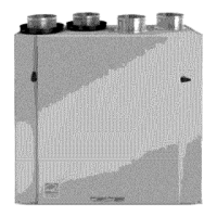
Defrost Cycle
Defrost cycle is controlled by a thermistor which is located in the
fresh-- air intake passage (the thermistor unit is connected to J4 of
control module (see Fig. 19 and 20). When defrost temperature
sensor detects the need for defrost, K5 relay will close for 6
minutes while K1 and K2 remain energized.
This closes the outdoor air damper while running HRV blower on
high-- speed. This process recirculates warm indoor air through heat
recovery core which melts any frost that has formed. Water created
in this process is collected by HRV and drained away. Frequency
of the defrost cycle depends on outdoor temperature (see Table 11).
HRV
 Loading...