EasyManua.ls Logo

Carrier HRVXXSVU1157 User Manual

Carrier HRVXXSVU1157
16 pages
To Next Page IconTo Next Page
Page #1 background imageLoading...
Page #1 background image
HRVXXSVU1157
Heat
Recovery
Ventilator
Installation
Instructions
HRVXXSVU1157
A11189
NOTE:
Read
the
entire
instruction
manual
before
starting
the
installation.
SAFETY
CONSIDERATIONS
Improper
installation,
adjustment,
alteration,
service,
maintenance,
or
use
can
cause
explosion,
fire,
electrical
shock,
or
other
conditions
which
may
cause
death,
personal
injury
or
property
damage.
Consult
a
qualified
installer,
service
agency
or
your
distributor
or
branch
for
information
or
assistance.
The
qualified
installer
or
agency
must
use
factory-authorized
kits
or
accessories
when
modifying
this
product. Refer
to
the
individual
instructions
packaged
with
the
kits
or
accessories
when
installing.
Follow
all
safety
codes.
Wear
safety
glasses,
protective
clothing,
and
work
gloves.
Have
a
fire
extinguisher
available.
Read
these
instructions
thoroughly
and
follow
all
warnings
and
cautions
included
in
literature
and
attached
to
the
unit.
Consult
local
building
codes
and
the
current
edition
of
the
National
Electrical
Code
(NEC)
NFPA
70.
In
Canada,
refer
to
the
current
editions
of
the
Canadian
Electrical
Code
CSA
C22.1.
Recognize
safety
information.
When
you
see
this
symbol
AN
on
the
unit
and
in
instructions
or
manuals,
be
alert
to
the
potential
for
personal
injury.
Understand
the
signal
words
DANGER,
WARNING,
and
CAUTION.
These
words
are
used
with
the
safety -alert
symbol.
DANGER
identifies
the
most
serious
hazards,
which
will
result
in
severe
personal
injury
or
death,
WARNING
signifies
hazards,
which
could
result
in
personal
injury
or
death.
CAUTION
is
used
to
identify
unsafe
practices,
which
may
result
in
minor
personal
injury
or
product
and
property
damage.
NOTE
is
used
to
highlight
suggestions
which
will
result
in
enhanced
installation,
reliability,
or
operation.
INTRODUCTION
The
Heat
Recovery
Ventilator
(HRV)
is
used
to
exchange
indoor
stale
air
with
outside
fresh
air.
The
HRV
unit
is
equipped
with
a
special
heat
recovery
core
which
transfers
sensible
heat
between
the
fresh
incoming
air
and
stale
exhaust
air.
It
is
required
to
locate
the
HRV
in
a
conditioned
space.
Special
attention
should
be
given
to
condensate
drain,
duct
application,
balancing
the
HRV,
and
locating
unit
for
easy
access
and
routine
maintenance.
The
cross-flow
design
core
allows
entering
and
leaving
air
streams
to
transfer
heat
energy
without
mixing.
LOCATION
Inspect
Equipment
Move
carton
to
final
installation
location.
Remove
the
HRV
from
carton
taking
care
not
to
damage
unit.
Remove
all
packaging
and
inspect
unit
for
damage.
Remove
parts
bag
from
inside
unit.
File
claim
with
shipping
company
if
shipment
is
damaged
or
incomplete.

Other manuals for Carrier HRVXXSVU1157

Question and Answer IconNeed help?

Do you have a question about the Carrier HRVXXSVU1157 and is the answer not in the manual?

Carrier HRVXXSVU1157 Specifications

General IconGeneral
Model NumberHRVXXSVU1157
BrandCarrier
CategoryFan
TypeHeat Recovery Ventilator
Voltage120V
Phase1
Frequency60 Hz
Motor TypeECM

Summary

Safety Considerations

General Safety Precautions

Follow all safety codes, wear protective gear, and have a fire extinguisher.

Understanding Safety Symbols and Signal Words

Explains DANGER, WARNING, CAUTION, and NOTE signal words.

Introduction to HRV

HRV Unit Functionality

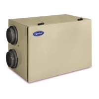
Explains the function and purpose of the HRV unit.

Unit Location and Inspection

Inspect Equipment

Instructions to inspect the unit for damage after unpacking.

Unit Location Guidelines

Recommendations for placing the HRV unit in a conditioned space.

Hazard Warnings and Precautions

Personal Injury and Electric Shock Warnings

Lists hazards like injury, shock, property damage, and improper use.

Equipment Damage Cautions

Lists cautions for equipment damage or improper operation.

Technical Data

Normal Operation and Defrost Cycles

Illustrates normal operation and details defrost cycle parameters.

Unit Dimensions

Provides dimensional drawings and specifications for the unit.

Typical Installation Methods

Fully Ducted System

Details installation for homes with radiant hot water or electric baseboard heat.

Central Draw Point System

Describes connection to a forced air system via registers.

Simplified Installation

Explains connection to a forced air system's return or supply duct.

Installation Procedures

Inspecting the Unit and Box Contents

Instructions to inspect the unit and its packaging for damage.

Unit Door Relocation

Steps for relocating the unit door for maintenance access.

Installation and Ductwork Calculations

Locating the Unit

Guidelines for choosing an appropriate location for the HRV unit.

Calculating Duct Size

Method for determining the correct duct size for airflow.

Ductwork Installation Details

Fully Ducted System Ductwork

Details on installing stale air exhaust and fresh air ducts.

Central Draw Point System Ductwork

Instructions for connecting to furnace supply/return ducts.

Connecting to Forced Air System

Simplified Installation: Supply Side Connection

Connects fresh air port to furnace supply duct.

Simplified Installation: Return Side Connection

Connects fresh air port to furnace return duct.

Simplified Installation: Stale Air Intake

Connects exhaust port to furnace return duct.

Simplified Installation: Fresh Air Distribution

Details on connecting to furnace for fresh air distribution.

Connecting Ducts to the Unit

Insulated Flexible Duct Installation

Procedure for connecting insulated flexible ducts to unit ports.

Non-Insulated Duct Installation

Using metal screws and tape for rigid ducts, tie wraps for flexible.

Exterior Hoods and Drain Connection

Installing Exterior Hoods

Guidelines for choosing location and installing intake/exhaust hoods.

Connecting the Drain

Procedure for connecting the drain tube and creating a water trap loop.

Unit Controls Overview

Unit Booting Sequence

Describes the 30-second booting sequence upon power up.

Integrated Control Operation

How to operate the unit using the push button and LED indicator.

Control Settings and Wiring

Setting Extended Defrost Mode

Procedure to set the unit to extended defrost in cold regions.

Electrical Connection to Main Controls

Instructions for wiring optional main wall controls.

Furnace Interlock Wiring

Connecting Optional Controls

Wiring optional dehumidistat, timer, or push-button switches.

Standard Furnace Interlock Wiring

Instructions for connecting the unit to a furnace's 24-volt system.

Alternate Furnace Interlock Wiring

Specific wiring for furnaces connected to a cooling system.

Wiring Diagrams and Motor Speed

Wiring Diagram Overview

Presents the complete wiring diagram for the unit.

Logic Diagram Overview

Illustrates the unit's logic and control flow.

Fan Motor Speed Selection

Details on how to select fan speeds and their corresponding CFM.

Unit Balancing Procedure

Equipment for Balancing

Lists required tools like a magnehelic gauge and plastic tubes.

Preliminary Balancing Stages

Steps before balancing, like sealing ducts and opening dampers.

Balancing Procedure Steps

Detailed steps for adjusting dampers and matching CFM values.

Service Parts

Exploded View of Parts

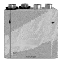
Diagram showing all components of the unit.

Parts List and Quantities

Table listing all available service parts and their quantities.

Troubleshooting Guide

LED Error Indicators and Unit Status

Explains LED flashes and their corresponding unit status.

Problem Diagnosis and Actions

Details specific problems, causes, actions, and unit status.

Temperature/Ohm Relationship

Temperature to Resistance Chart

Table showing Ohm values for various temperatures for the thermistor.

Related product manuals