EasyManua.ls Logo

Carrier HRVCCSVU User Manual

Carrier HRVCCSVU
18 pages
To Next Page IconTo Next Page
Page #1 background imageLoading...
Page #1 background image
HRVCCLHA
HRVCCSVU
HRVCCLVU
Heat Recovery Ventilator
Installation Instructions
A05260
HRVCCLHA -- Conventional Unit
A92268
HRVCCSVU -- Compact Unit
A92377
HRVCCLVU -- High Efficiency Unit
NOTE: Read the entire instruction manual before starting the
installation.
SAFETY CONSIDERATIONS
Improper installation, adjustment, alteration, service, maintenance,
or use can cause explosion, fire, electrical shock, or other
conditions which may cause death, personal injury or property
damage. Consult a qualified installer, service agency or your
distributor or branch for information or assistance. The qualified
installer or agency must use factory--authorized kits or accessories
when modifying this product. Refer to the individual instructions
packaged with the kits or accessories when installing.
Follow all safety codes. Wear safety glasses, protective clothing,
and work gloves. Have a fire extinguisher available. Read these
instructions thoroughly and follow all warnings and cautions
included in literature and attached to the unit. Consult local
building codes and the current edition of the National Electrical
Code (NEC) NFPA 70.
In Canada, refer to the current editions of the Canadian Electrical
Code CSA C22.1.
Recognize safety information. When you see this symbol
on
the unit and in instructions or manuals, be alert to the potential for
personal injury. Understand the signal words DANGER,
WARNING,andCAUTION. These words are used with the
safety-- alert symbol. DANGER identifies the most serious hazards,
which will result in severe personal injury or death. WARNING
signifies hazards, which could result in personal injury or death.
CAUTION is used to identify unsafe practices, which may result
in minor personal injury or product and property damage. NOTE
is used to highlight suggestions which will result in enhanced
installation, reliability , or operation.
INTRODUCTION
The Heat Recovery Ventilator (HRV) is used to exchange indoor
stale air with outside fresh air. The HRV unit is equipped with a
special heat recovery core which transfers sensible heat between
the fresh incoming air and stale exhaust air.
It is required to locate the HRV in a conditioned space. Special
attention should be given to condensate drain, duct application,
balancing the HRV, and locating unit for easy access and routine
maintenance. The cross--flow design core allows entering and
leaving air streams to transfer heat energy without mixing.
LOCATION
Inspect Equipment
Move carton to final installation location. Remove the HRV from
carton taking care not to damage unit. Remove all packaging and
inspect unit for damage. Remove parts bag from inside unit. File
claim with shipping company if shipment is damaged or
incomplete.
Question and Answer IconNeed help?

Do you have a question about the Carrier HRVCCSVU and is the answer not in the manual?

Carrier HRVCCSVU Specifications

General IconGeneral
BrandCarrier
ModelHRVCCSVU
CategoryFan
LanguageEnglish

Summary

Installation Instructions

Safety Considerations

General safety precautions and warnings for installation.

Introduction to HRV

Overview of the Heat Recovery Ventilator (HRV) function.

Location Selection

Guidance on selecting an appropriate installation space for the HRV.

Component Descriptions

HRVCCLHA Unit Components

Identifies components of the HRVCCLHA model.

HRVCCSVU Unit Components

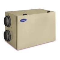
Identifies components of the HRVCCSVU model.

HRVCCLVU Unit Components

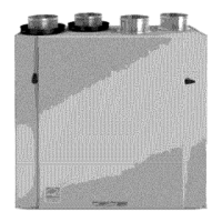
Identifies components of the HRVCCLVU model.

Airflow Diagrams

Illustrations of HRV airflow during different operational modes.

Unit Installation Procedures

Safety Warnings and Cautions

Covers critical hazards and precautions for safe installation.

Mounting and Location

Guidance on physical mounting and optimal space selection for the unit.

Installation Diagrams

Diagrams illustrating chain spring installation and airflow.

System Integration

Forced-Air Application

Instructions for integrating the HRV with a forced-air HVAC system.

Duct Connection Guidelines

Precautions and methods for connecting HRV ducts, including insulation needs.

Drainage and Controls

Condensate Drain Setup

Step-by-step instructions for properly connecting the condensate drain.

Exterior Hood Installation

Important considerations for locating and installing exterior air intake/exhaust hoods.

Wall Control Operations

How to operate the various types of HRV wall controls.

Control Board Configuration and Defrost

Control Board Jumper Setup

Explains jumper configuration on the control board.

Defrost Cycle Mechanism

Details the HRV's defrost cycle logic and operation.

Infinity Control Integration

Instructions for operating the HRV using the Infinity System Control.

Advanced Controls and Wiring

Cooling Mode Operation

Description of operational modes specific to cooling conditions.

Wall Control Wiring

Detailed instructions and diagrams for wiring the HRV wall control.

Accessory Timers

Guidance on installing and using optional 20-minute and 60-minute timers.

Airflow Balancing

Balancing Importance

Explains why balancing airflow is crucial for system performance.

Balancing Dampers

Information on balancing dampers for optimal HRV operation.

Airflow Measurement and Ventilation Evaluation

Flow Collar Usage

Instructions on using flow collars for accurate airflow measurement.

Ventilation Calculation Methods

Two methods for calculating a home's ventilation requirements.

HRVCCLHA Wiring Diagram

Model Specific Connections

Detailed wiring diagram for specific HRVCCLHA models.

HRVCCSVU/CCLVU Wiring Diagrams

Model Specific Connections

Detailed wiring diagrams for specific HRVCCSVU/CCLVU models.

Unit Operation and Maintenance

Recirculation/Defrost Airflow & Logic

Illustrations and logic for recirculation and defrost airflow modes.

General Care and Safety Procedures

Covers general unit care, safety precautions, door, and filter maintenance.

Maintenance and Troubleshooting

Component Care and Cleaning

Instructions for cleaning unit components like blower motor and core.

Troubleshooting Guide

Section dedicated to diagnosing and resolving common unit issues.

Troubleshooting Safety Precautions

Safety warnings for electrical shock and cut hazards during troubleshooting.

Troubleshooting Details

Problem Resolution Chart

A chart listing common problems and their potential causes and solutions.

Technical Specifications and Adjustments

Temperature and Resistance Data

Table showing thermistor resistance values at different temperatures.

Unit Testing and Speed Settings

Procedures for override testing and adjusting blower speed settings.

Defrost Cycle Parameters

Explanation of defrost cycle control based on temperature.

Configuration and Error Handling

Defrost Cycle Table

Table detailing defrost cycle frequency and duration based on temperature.

Jumper Configuration Details

Information on control module jumper settings for proper configuration.

Safety and Error Signaling

Describes safety features and how wall controls signal unit errors.

Wiring and Reset Procedures

System Wiring Connections

Table detailing system wiring colors and connections for controls.

Troubleshooting Cases

Specific troubleshooting scenarios for wall control and HRV response.

Unit Reset Procedure

Step-by-step instructions for resetting the HRV unit.

Related product manuals