2
COMPONENT DESCRIPTION
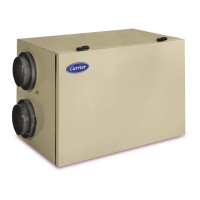
The following listed items are components of HRVCCLHA (see
Fig. 1).
2
3
10
8
1
4
57 9 6
A05349
Fig. 1 -- HRVCCLHA Conventional Ho rizontal Unit
1. Stale air return from building connected to return--air duct
system.
2. Fresh-- air intake connected to outdoor air inlet hood.
3. Exhaust-- air connected to outdoor air exhaust hood.
4. Mechanical filters trap dust contained in the air.
5. Heat recovery core is a cross--flow type. The core transfers
heat between the 2 air streams. See Figures 2 and 3.
STALE AIR
TO OUTSIDE
FRESH AIR
TO BUILDING
FRESH AIR
FROM OUTSIDE
STALE AIR
FROM BUILDING
A05353
Fig. 2 -- HRVCCLHA Airflow During Air Exchange
FILTERED AIR
TO BUILDING
STALE AIR
FROM BUILDING
A05354
Fig. 3 -- HRVCCLHA Airflow During Defrost
6. Blowers bring in fresh-- air from outside and exhaust
stale--air to outside.
7. Electronic control circuit ensures proper unit operation.
8. Fresh-- air supply from HRV connected to return-- air duct of
forced--air system.
9. Terminal connector block for wiring wall and timer
controls.
10. Electrical cord connects to standard 115V outlet.
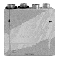
The following listed items are components of HRVCCSVU and
HRVCCLVU. See Figures 4 and 5).
1. Stale--air return from building connected to return--air duct
system.
2. Fresh-- air intake connected to outdoor air inlet hood.
3. Exhaust-- air connected to outdoor air exhaust hood.
4. Dampers are used to control air exchange with outdoor air
during defrost mode.
4
5
10
3
2
1
11
13
7
14
12
8 9
6
A98408
Fig. 4 -- HRVCCSVU Compact Unit
1
12
3
14
2
4
6
11
13
8
9
10
7
5
A98409
Fig. 5 -- HRVCCLVU Compa ct High --Efficiency Unit
5. Mechanical filters trap dust contained in the air.
6. Heat recovery core is either a cross--flow type for compact
models, or a counter-- flow type for high -- efficiency models.
The core transfers heat between the 2 air streams. See Fig-
ures 6 and 7.
7. Blowers bring in fresh-- air from outside and exhaust
stale--air to outside.
8. Capacitor required for motor operation.
9. Condensation tray collects condensate from heat recovery
core.
10. Drainage tubes connect to sleeved grommets.
11. Electronic control circuit ensures proper unit operation.
12. Fresh air supply from HRV connect to return--air duct of
forced--air system.
13. Terminal connector block for wiring wall and timer
controls.
14. Electrical cord connects to standard 115V outlet.
HRV
 Loading...