24VNA6: Installation Instructions
Manufacturer reserves the right to change, at any time, specifications and designs without notice and without obligations.
18
A160118
A160119
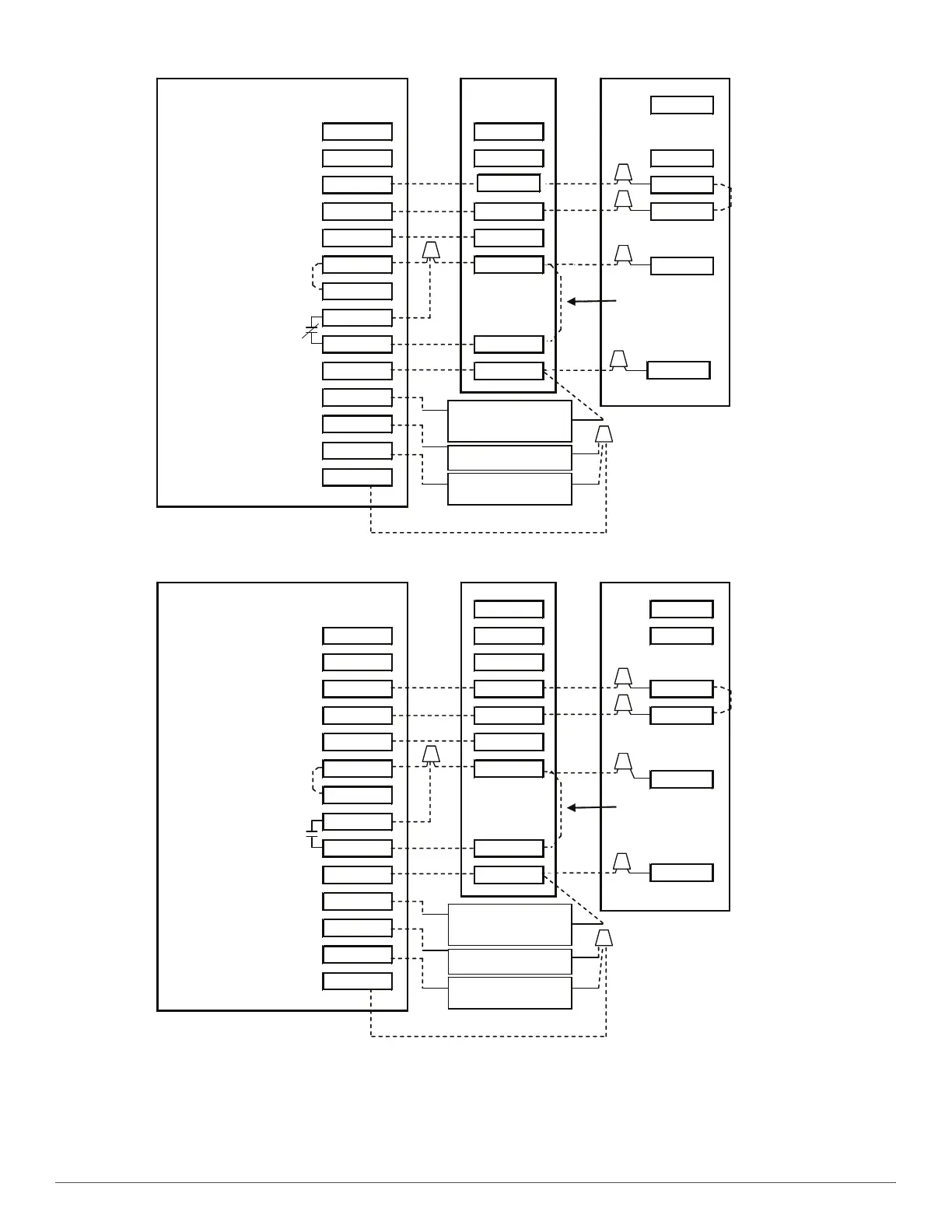
Fig. 31 – Variable Speed Unit Connected to a Conventional Thermostat in Emergency Mode
Thermidistat Furnace A/C
O
RVS Cooling O/B W2 W2
Heat Stage 3
(furnace)
W/W1 W/W1 W1
Heat/Cool Stage 1 Y1 / W2 Y1
Heat/Cool Stage 2 Y/Y2 Y/Y2 Y2
Fan G G
24VAC Hot Heating Rh R
24VAC Hot Cooling Rc
Dry Contact 1 D1
Dry Contact 2 D2
DHUM
24VAC Common C COM
Humidify HUM
Outdoor Air Temp OAT
Remote Room Sensor RRS
OAT/RRS Com SRTN
Humidifier Solenoid
Valve
Y1
J1 Jumper
on Control Board
Jumper Wire
Required for
Single-Stage
C
BLU
YEL
R
RED
BLK
OO
RVS Cooling O/B W2 W1 W1
Heat Stage 3 W/W1 W2
Heat/Cool Stage 1 Y1 / W2 Y1 Y1
Heat/Cool Stage 2 Y/Y2 Y/Y2 Y2
Fan G G
24VAC Hot Heating Rh R
24VAC Hot Cooling Rc
Dry Contact 1 D1
Dry Contact 2 D2 DH
24VAC Common C C
Humidify HUM
Outdoor Air Temp OAT
Remote Room Sensor RRS
OAT/RRS Com SRTN
Thermidistat Fan Coil A/C
Humidifier Solenoid
Valve
J1 Jumper
on Control Board
C
R
Jumper Wire
Required for
Single-Stage
BLU
RED
YEL
BLK
 Loading...