24VNA6: Installation Instructions
Manufacturer reserves the right to change, at any time, specifications and designs without notice and without obligations.
4
On rooftop applications, mount on level platform or frame. Place unit
above a load-bearing wall and isolate unit and tubing set from structure.
Arrange supporting members to adequately support unit and minimize
transmission of vibration to building. Consult local codes governing
rooftop applications.
Roof mounted units exposed to winds above 5 mph may require wind
baffles. Consult the Service Manual - Residential Split System Air
Conditioners and Heat Pumps Using Puron® Refrigerant for wind baffle
construction.
NOTE: Unit must be level to within ±2° (±3/8 in./ft,±9.5 mm/m.) per
compressor manufacturer specifications.
Step 3 – Clearance Requirements
When installing, allow sufficient space for airflow clearance, wiring,
refrigerant piping, and service. Allow 24 in. (609.6 mm) clearance to
service end of unit and 48 in. (1219.2 mm) (above unit. For proper
airflow, a 6-in. (152.4 mm) clearance on 1 side of unit and 12-in. (304.8
mm) on all remaining sides must be maintained. Maintain a distance of
24 in. (609.6 mm) between units. Position so water, snow, or ice from
roof or eaves cannot fall directly on unit.
On rooftop applications, locate unit at least 6 in. (152.4 mm) above roof
surface.
Step 4 – Operating Ambient
The minimum outdoor operating ambient in cooling mode is 55°F
(12.78°C) without low ambient cooling enabled, and the maximum
outdoor operating ambient in cooling mode is 125°F (51.67°C).
Step 5 – Elevate Unit
Elevate unit per local climate and code requirements to provide
clearance above estimated snowfall level and ensure adequate drainage
of unit.
Step 6 – In Long-Line Applications, Install Liquid-Line
Solenoid Valve (LSV)
For refrigerant piping arrangements with equivalent lengths of greater
than 80 ft. (24.38 m) and/or when elevation difference between indoor
and outdoor unit is greater than ±20 ft. (±6.10 m), follow the piping
configuration and liquid line solenoid valve (LSV) accessory
requirements from the Residential Piping and Long-line guideline. CCH,
start gear and piston changes do not apply. If required by Long-Line
Guideline, install LSV kit, part no. KHALS0401LLS. LSV should be
installed within 2 ft. (0.61 m) of outdoor unit with flow arrow pointing
toward outdoor unit.
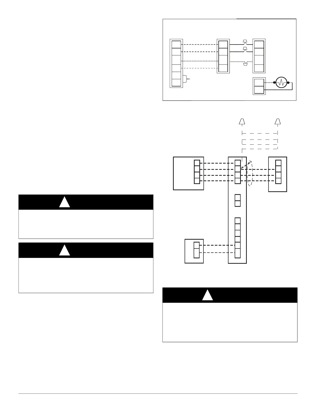
Make the necessary electrical connections as shown in Fig. 4 and Fig. 5
and by following the Installation Instructions included with accessory
kit.
IMPORTANT: Flow arrow must point toward outdoor unit.
A180243
Fig. 4 – Liquid Line Solenoid Electrical Connection
(Required for long line applications)
A150776
Fig. 5 – Infinity Furnace or Fan Coil Wiring with Communicating
Variable Speed AC
Step 7 – Make Piping Connections
CAUTION
!
UNIT OPERATION HAZARD
Failure to follow this caution may result in equipment damage or
improper operation.
Do not allow water and/or ice to build up in base pan.
CAUTION
!
UNIT OPERATION HAZARD
Failure to follow this caution may result in equipment damage or
improper operation.
Locate the unit in such a way that it is stable in all circumstances
including adverse weather conditions.
WARNING
!
PERSONAL INJURY AND UNIT DAMAGE
HAZARD
Failure to follow this warning could result in personal injury or death.
Relieve pressure and recover all refrigerant before system repair or
final unit disposal. Use all service ports and open all flow-control
devices, including solenoid valves.
Furnace or
Fan Coil
Variable Speed
AC or HP
D
C
B
A
Wall Control
HP or AC
OAT
RYOWCHUM
C
Humidifier
24vac
Furnace or Fan Coil
’C’ connection optional
Sheild Cable
D not required
Unused Wires
WT
YL
GN
D
C
B
A
 Loading...