15
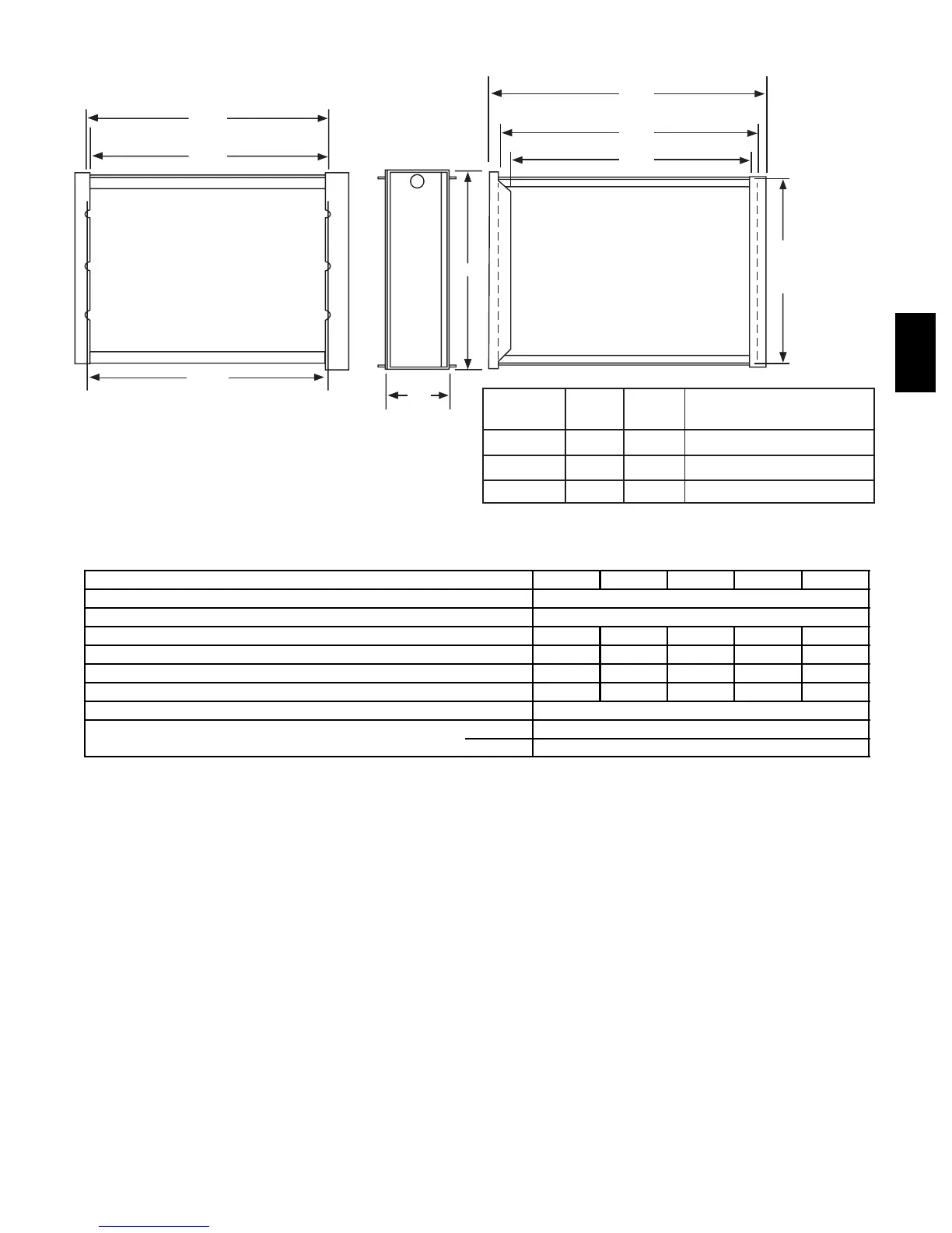
MEDIA FILTER CABINET
A
Media
Filter Cabinet
A
B
16 17 16
20 21 20
24 25 24
23
5
/
8
"
23
3
/
8
"
Furnace Side
23
3
/
4
"
Centerline Screw Slots
25
5
/
8
"
Duct Side
24
3
/
8
"
Opening with Flanges Bent
23
1
/
8
"
Opening
5
3
/
4
"
gninepO B
Shipped With Sizes
120-20
060-14
080-14
(In.)
(In.)
(In.)
A06493
ELECTRICAL DATA
UNIT SIZE 060---14 080---14 080---20 100---20 120---20
U n i t V o l t s --- H e r t z --- P h a s e 1 1 5 --- 6 0 --- 1
Operating Voltage Range (Min --- Max)* 104---127
Maximum Unit Amps 8.9 8.9 13.8 13.8 13.8
Minimum Wire Size 14 14 12 12 12
Maxium Wire Length (ft){ 31 31 32 32 32
Maximum Fuse or Ckt Brk (Amps)} 15 15 20 20 20
Transformer (24v) 40va
External Control Power Available Heating 25va
Cooling 34va
* Permissible limits of the voltage range at which the unit will operate satisfactorily.
{ Length shown is as measured 1 way along wire path between unit and service panel for maximum 2% voltage drop.
} Time---delay type is recommended.
58UVB