12
12
A05053
17
5
⁄
16
"
24
1
⁄2"
27
9
⁄
16
"
TYP
27
5
⁄
8
"
29
11
⁄16"
TYP
30
13
⁄16"
32
5
⁄8"
TYP
33
1
⁄4"
TYP
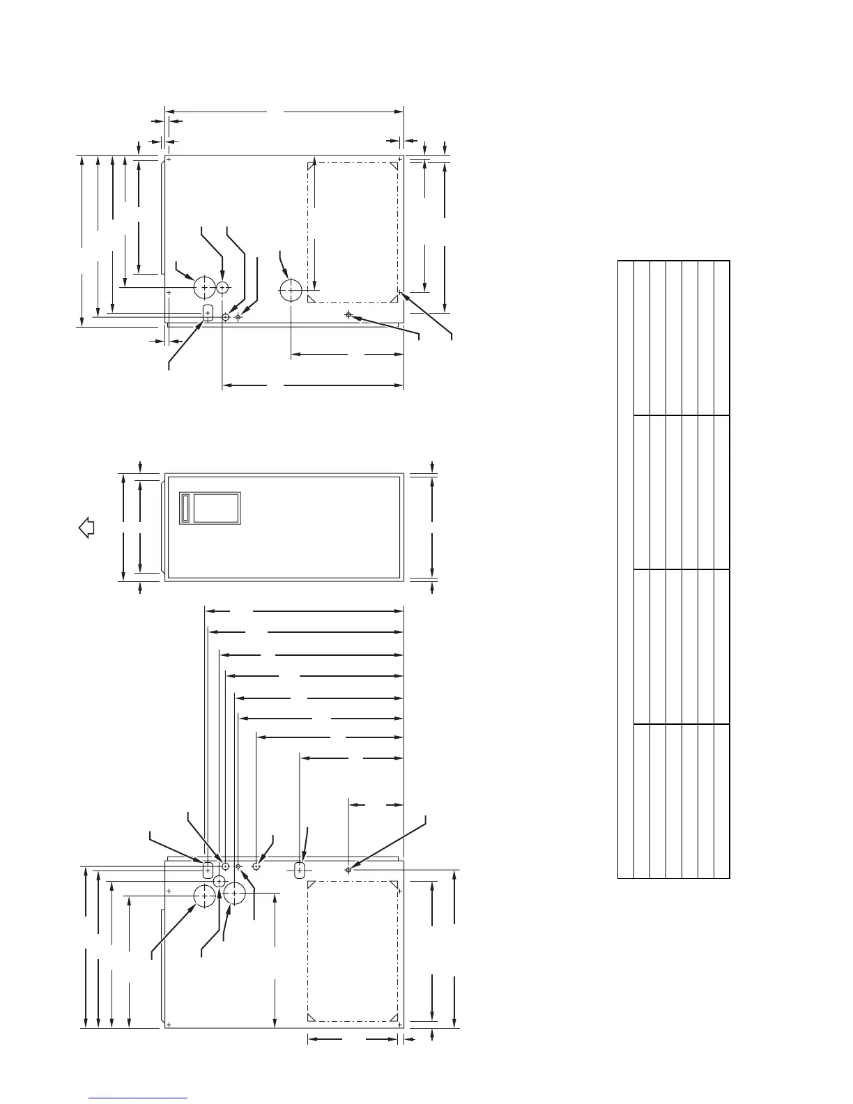
CONDENSATE
DRAIN TRAP
LOCATION
(ALTERNATE
UPFLOW)
7
⁄8-IN. DIA
ACCESSORY
POWER ENTRY
7
⁄8-IN. DIA
POWER CONN
CONDENSATE DRAIN
TRAP LOCATION
(DOWNFLOW &
HORIZONTAL LEFT)
26
15
⁄16"
24
1
⁄
2
"
22
5
⁄
16
"
2
-IN. COMBUSTION-
AIR CONN
1
⁄2
-IN. DIA
GAS CONN
2
-IN. VENT CONN
1
⁄2-IN. DIA THERMOSTAT
ENTRY
22
11
⁄16"
SIDE INLET
23
1
⁄4" TYP
SIDE INLET
1
1
⁄
4
"
1" E
INLET
11
⁄16"
11
⁄16"
D
13
⁄
16
"
13
⁄
16
"
OUTLET
A
AIRFLOW
OUTLET
26
15
⁄
16
"
28
1
⁄
2
"
22
5
⁄
16
"
19"
13
⁄
16
"
5
⁄
8
"
5
⁄16"
1"
39
7
⁄8"
22
1
⁄4" TYP
11
⁄
16
"
7
⁄
16
"
24
3
⁄
16
"
BOTTOM INLET
18
1
⁄
4
"
22
11
⁄
16
"
CONDENSATE DRAIN
TRAP LOCATION
(DOWNFLOW &
HORIZONTAL RIGHT)
OR ALTERNATE
1
⁄2
-IN. DIA GAS CONN
2-IN. COMBUSTION-
AIR CONN
1
⁄2-IN. DIA
GAS CONN
7
⁄8-IN. DIA
POWER CONN
1
⁄2-IN. DIA
THERMOSTAT ENTRY
2-IN. VENT CONN
DIMPLE LOCATORS
FOR HORIZONTAL
HANGING
14
1
⁄2"
TYP
SIDE INLET
NOTES: 1. Minimum return-air openings at furnace, based on metal duct. If flex duct is used,
see flex duct manufacturer’s recommendations for equivalent diameters.
2. Minimum return-air opening at furnace:
a. For 800 CFM–16-in. round or 14
1
/ 2 x 12-in. rectangle.
b. For 1200 CFM–20-in. round or 14
1
/ 2 x 19
1
/ 2-in. rectangle.
c. For 1600 CFM–22-in. round or 14
1
/ 2 x 23
1
/ 4-in. rectangle.
d. For airflow requirements above 1800 CFM, see Air Delivery table in Product Data
literature for specific use of single side inlets. The use of both side inlets, a
combination of 1 side and the bottom, or the bottom only will ensure adequate
return air openings for airflow requirements above 1800 CFM at 0.5 W.C. ESP.
9
7
⁄
16
"
TYP
26
15
⁄16" TYP
CONDENSATE
DRAIN LOCATION
(UPFLOW)
30
1
⁄
2
"
9
⁄
16
"
TYP
CONDENSATE
DRAIN LOCATION
(UPFLOW)
26
1
⁄
4
"
26
1
⁄4"
DIMENSIONS (IN / MM)
UNIT SIZE A D E
060--- 14 17---1/2 / 444.5 15---7/8 / 403.3 16 / 406.4
080--- 14 21 / 533.4 19---3/8 / 492.2 19---1/2 / 495.3
080--- 20 21 / 533.4 19---3/8 / 492.2 19---1/2 / 495.3
100--- 20 21 / 533.4 19---3/8 / 492.2 19---1/2 / 495.3
120--- 20 24---1/2 / 622.3 22---7/8 / 581.0 23 / 584.2
 Loading...


