3
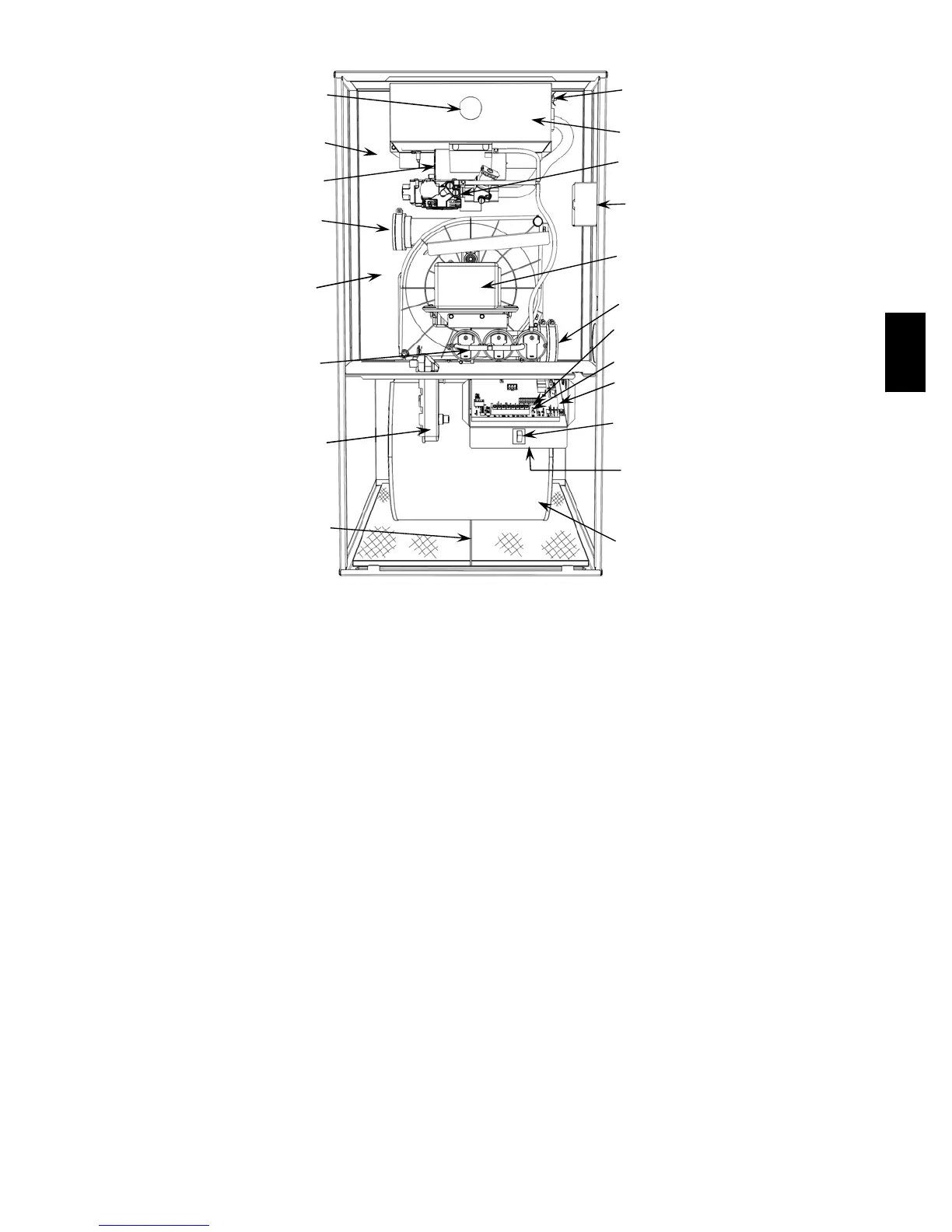
FURNACE COMPONENTS
1
2
3
4
5
6
7
8
9
10
11
12
13
14
16
17
18
19
5
15
A07609
1. Combustion --air intake connection to ensure contaminant--
free air (right or left side).
2. Burner sight glass for viewing burner flame.
3. Burner assembly (inside). Operates with energy--saving
inshot burners and Power Heatt igniter for safe,
dependable heating.
4. VariPhaset multi-- stage redundant valve assembly. Safe
and ef ficient. Features one primary gas control with two
internal shutoff valves and a throttling valve.
5. Vent outlet. Uses PVC pipe to carry flue gas from the
furnace’s combustion system (right or left side).
6. Inducer motor. Pulls hot flue gases through the heat
exchangers, maintaining negative pressure for added safety.
7. Blower access panel safety interlock switch.
8. Air filter and retainer (location in furnace may vary).
9. Condensate drain connection. Collects moisture condensed
from burned gases for disposal into home drain system.
(Location in furnace varies.)
10. Heavy--duty blower. Circulates air across the heat
exchangers to transfer heat into the home.
11. Serpentufft secondary condensing heat exchanger (inside).
Wrings out more heat through condensation. Constructed
with polypropylene-- laminated steel to ensure durability.
12. Primary serpentine heat exchanger (inside). Stretches fuel
dollars with the S--shaped heat--flow design. Solid
construction of corrosion--resistant aluminized steel means
reliability.
13. Furnace control board.
14. 3--amp fuse provides electrical and component protection.
15. Light emitting diode (LED) on furnace control board.
Status code light is for diagnosing furnace operation and
service requirements.
16. Pressure switches ensure adequate flow of flue gas through
furnace and out vent system.
17. Rollout switch (manual reset) to prevent overtemperature.
18. Junction box for 115 --v electrical power supply. (May be
located on right or left side)
19. Transformer (24v) behind furnace control board provides
low--voltage power to furnace control board and thermostat.
58MVC

 Loading...


