16
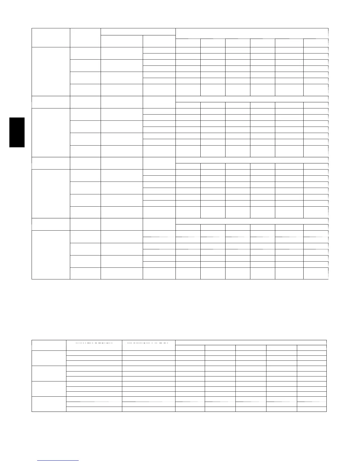
Maximum Allowable Pipe Length (Ft / M) (Continued)
ALTITUDE
UNIT SIZE
(BTUH)
Direct Vent (2--Pipe Only)
NUMBER OF 90_ ELBOWS
Termina tion
Type
Pipe Dia
(IN.)*
1 2 3 4 5 6
6001 to 7000‡
60,000
2 P i p e o r 2 --- I n .
Concentric
1 --- 1 / 2 35 / 10.7 30 / 9.1 25 / 7.6 20 / 6.1 15 / 4.6 10 / 3.0
2 70 / 21.3 70 / 21.3 68 / 20.7 67 / 20.4 66 / 20.11 64 / 19.5
80,000
2 P i p e o r 2 --- I n .
Concentric
1 --- 1 / 2 20 / 6.1 15 / 4.6 10 / 3.0 5/1.5 NA NA
2 70 / 21.3 70 / 21.3 68 / 20.7 67 / 20.4 62 / 18.9 57 / 17.4
100,000
2 P i p e o r 2 --- I n .
Concentric
2 31 / 9.4 26 / 7.9 21 / 6.4 16 / 4.9 11 / 3.4 6/1.8
2 --- 1 / 2 70 / 21.3 70 / 21.3 68 / 20.7 67 / 20.4 66 / 20.1 64 / 19.5
120,000
2 P i p e o r 3 --- I n .
Concentric
3onedisk† 49 / 14.9 48 / 14.6 47 / 14.3 45 / 13.7 44 / 13.4 43 / 13.1
ALTITUDE
UNIT SIZE
(BTUH)
Termina tion
Type
Pipe Dia
(IN.)*
NUMBER OF 90_ ELBOWS
1 2 3 4 5 6
7001 to 8000‡
60,000
2 P i p e o r 2 --- I n .
Concentric
1 --- 1 / 2 32 / 9.8 27 / 8.2 22 / 6.7 17 / 5.2 12 / 3.7 7/2.1
2 66 /20.1 65 / 19.8 63 / 19.2 62 / 18.9 60 / 18.3 59 / 18.0
80,000
2 P i p e o r 2 --- I n .
Concentric
1 --- 1 / 2 18 / 5.5 13 / 4.0 8/2.4 NA NA NA
2 66 / 20.1 65 / 19.8 63 / 19.2 62 / 18.9 57 / 17.4 52 / 15.8
100,000
2 P i p e o r 2 --- I n .
Concentric
2 29 / 8.8 24 / 7.3 19 / 5.8 14 / 4.3 9/2.7 NA
2 --- 1 / 2 66 / 20.1 65 / 19.8 63 / 19.2 62 / 18.9 60 / 18.3 59 / 18
120,000
2 P i p e o r 3 --- I n .
Concentric
3onedisk† 46 / 14.0 44 / 13.4 43 / 13.1 41 / 12.5 40 / 12.2 38 / 11.6
ALTITUDE
UNIT SIZE
(BTUH)
Termina tion
Type
Pipe Dia
(IN.)*
NUMBER OF 90_ ELBOWS
1 2 3 4 5 6
8001 to 9000‡
60,000
2 P i p e o r 2 --- I n .
Concentric
1 --- 1 / 2 30 / 9.1 25 / 7.6 20 / 6.1 15 / 4.6 10 / 3.0 5/1.5
2 62 / 18.9 60 / 17.8 58 / 17.7 56 / 17.1 55 / 16.8 53 / 16.2
80,000
2 P i p e o r 2 --- I n .
Concentric
1 --- 1 / 2 17 / 5.2 12 / 3.1 7/2.1 NA NA NA
2 62 / 18.9 60 / 18.3 58 / 17.7 56 / 17.1 51 / 15.5 46 / 14.0
100,000
2 P i p e o r 2 --- I n .
Concentric
2 27 / 8.2 22 / 6.7 17 / 5.2 12 / 3.7 7/2.1 NA
2 --- 1 / 2 62 / 18.9 60 / 18.3 58 / 17.7 56 / 17.1 55 / 16.8 53 / 16.2
120,000
2 P i p e o r 3 --- I n .
Concentric
3onedisk† 43 / 13.1 41 / 12.5 39 /11.9 37 / 11.3 35 / 10.7 34 / 10.4
ALTITUDE
UNIT SIZE
(BTUH)
Termina tion
Type
Pipe Dia
(IN.)*
NUMBER OF 90_ ELBOWS
1 2 3 4 5 6
9001 to
10000‡
60,000
2 P i p e o r 2 --- I n .
Concentric
1 --- 1 / 2 27 / 8.2 22 / 6.7 17 / 5.2 12 / 3.7 7/2.1 NA
2 57 / 17.4 55 / 16.8 53 / 16.2 51 / 15.5 49 / 14.9 47 / 14.3
80,000
2 P i p e o r 2 --- I n .
Concentric
1 --- 1 / 2 15 / 4.6 10 / 3.0 5/1.5 NA NA NA
2 57 / 17.4 55 / 16.8 53 / 16.2 51 / 15.5 46 / 14.0 41 / 12.5
100,000
2 P i p e o r 2 --- I n .
Concentric
2 24 / 7.3 19 / 5.8 14 / 4.3 9/2.7 NA NA
2 --- 1 / 2 57 / 17.4 55 / 16.8 53 / 16.2 51 / 15.5 49 / 14.9 47 / 14.3
120,000
2 P i p e o r 3 --- I n .
Concentric
3onedisk† 39 / 11.9 37 / 11.3 35 / 10.7 33 / 10.1 31 / 9.5 29 / 8.8
* Disk usage ---Unless otherwise stated, use perforated disk assembly (factory ---supplied in loose parts bag).
{ Wide radius elbow.
} Vent sizing for Ca nadian installations over 4500 ft (1370m) above sea level are subject to a cceptance by th e local author ities having jur isdiction.
NA---Not Allowed; pressure switch will not make.
NOTES:
1. Do not use pipe size greater than those specified in table or incomplete combustion, flame disturbance, or flame sense lockout may occur.
2. Size both the combustion---air and vent pipe independently, determine the smallest diameter allowed by the table for each pipe, then use the larger diameter for both pipes.
3. Assume two 45_ elbows equal one 90_ elbow. Long radius elbows are desirable and may be required in some cases.
4. Elbows and pipe sections within the furnace casing and at the vent termination should not be included in vent length or elbow count.
5. The minimum pipe length is 5 ft for all applications.
Maximum Allowable Exposed Vent Pipe Length (Ft / M) with Insulation in
Winter Design Temperature Ambient*
UNIT SIZE
WINTER DESIGN MAXIMUM PIPE DI-
INSULATION THICKNES S†
TEMPERATURE
AMETER (IN.)
0 3/8 1/2 3/4 1
060---14
20_F / --- 6 . 7 _C 2 30 / 9.1 55 / 16.8 61 / 18.6 70 / 21.3 70 / 21.3
0_F / --- 1 7 . 8 _C 2 16 / 4.9 33 / 10.1 38 / 11.6 46 / 14.0 53 / 16.2
--- 2 0 _F / --- 2 8 . 9 _C 2 9/2.7 23 / 7.0 26 / 7.9 33 / 10.1 38 / 11.6
080---14
080---20
20_F / --- 6 . 7 _C 2 37 / 11.2 65 / 19.8 70 / 21.4 70 / 21.3 70 / 21.3
0_F / --- 1 7 . 8 _C 2 20 / 6.1 39 / 11.9 45 / 13.7 55 / 16.8 63 / 19.2
--- 2 0 _F / --- 2 8 . 9 _C 2 11 / 3.4 27 / 8.3 31 / 9.4 39 / 11.9 45 / 13.7
100---20
20_F / --- 6 . 7 _C 2 --- 1 / 2 41 / 12.5 70 / 21.3 70 / 21.3 70 / 21.3 70 / 21.3
0_F / --- 1 7 . 8 _C 2 --- 1 / 2 21 / 6.4 42 / 12.8 48 / 14.6 59 / 18.0 68 / 20.7
--- 2 0 _F / --- 2 8 . 9 _C 2 --- 1 / 2 11 / 3.4 28 / 8.5 33 / 10.1 41 / 12.5 49 / 14.9
120---20
20_F / --- 6 . 7 _C 3 49 / 14.9 70 / 21.3 70 / 21.3 70 / 21.3 70 / 21.3
0_F / --- 1 7 . 8 _C 3 26 / 7.9 51 / 15.5 58 / 17.7 70 / 21.3 70 /21.3
--- 2 0 _F / --- 2 8 . 9 _C 3 15 / 4.6 35 / 10.7 40 / 12.2 50 / 15.2 59 / 18.0
* Pipe length (ft/m) specified for maximum pipe lengths located in unconditioned spaces. Pipes l ocated in un conditioned space cannot exceed total allowable
pipe length as specified in Table ?.
†Insulation thickness based on R value of 3.5 per in.
58MVC

 Loading...


